Chocolate Fireguard comes to mind
Of late I have been going round in circles on a project to keep our local church clock roughly on time. I say roughly as my idea of timekeeping does not accord with the aspirations of the village residents. Quote ‘ I only need to know when it is the time to go inside for a brew’ / ‘knock off for the day’ / ‘get my skates on or I will be late for work’ etc. I was thinking sub seconds and they were thinking a minute or so as being perfectly adequate. The exception is at 11am on the 11th of November when it has to be exact.
That as it may be, the project is moving along. The first problem was what to measure on the clock to reference the time adjustment. The pendulum (1.25s rate) is clearly the easiest choice and a sensor beam being broken by the pendulum swing will solve this problem. The slight problem is that the sensor will not necessarily ‘switch’ at the same time when being approached from the two directions of the pendulum swing. My Arduino skills might struggle to come up with some code to discriminate this so I reverted to simple CMOS logic. An ICM7555 acts as a monostable that has a period greater than one swing. This is triggered by the falling edge of the swing pulse derived from a simple differentiator network. The monostable extended period pulse is then gated with the incoming pulse using a CD4001 Quad NOR to always give me half the pulse rate regardless of the swing direction. That probably makes no sense at all so here is my back of an envelope waveform diagram and circuitry.
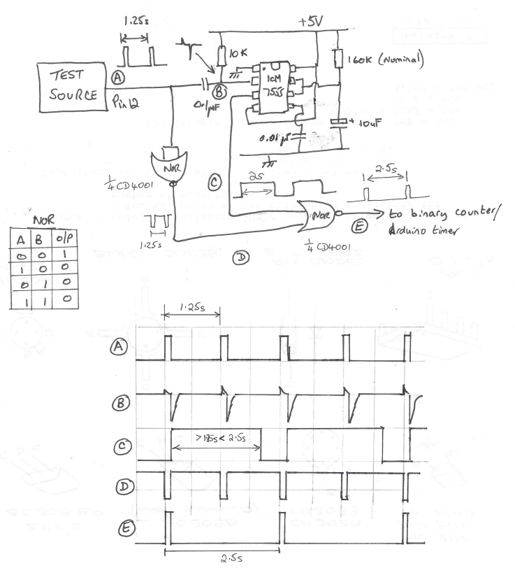
The circuit has turned out quite useful for other applications. I also refined it to have a CD4024 ripple counter fed from the output at E. This allowed extended logging periods to be achieved. I also utilised the unused gates on the CD4001 to provide an isolating buffer on the input signal. This meant the differentiating network would always see the same drive signal regardless of the incoming waveform and its source impedance.
Progress indeed. I now had a pulse train representing the clock beat period. All I had to do was measure the time taken between pulses and I could compare and adjust the pendulum rate.
Having got a reliable 2.5s pulse it was time to reverted to an Ardiuno UNO to measure the period. With some help from a friend we ran a sketch using millis to record the time between pulses. This minimalist sketch did not seem all that repeatable. I also did some tests with Frequency.h sketch code from the PJRC website (very useful source) and had similar poor results. I was using a FY6900 as my reference 1.25Hz signal and to get a 1.25Hz reading I had to offset the FY6900 quite a way from nominal. What to believe?
In a bid to get a known good reference I powered up my Arduino GTU-7 GPS module and measured the 1 second output pulse using both of the above sketches and the results were not much closer to the truth. I tried an Arduino MEGA instead of the UNO and got a different set of inaccurate results
This led me to think that the UNO and the MEGA must be the cause. Looking at these two boards, both have a 16MHz crystal which I (foolishly) believed was the processor reference and therefore could not be that much off frequency. Totally wrong. The crystal is for the USB interface, not the processor. Instead the processor has a basic 16MHz resonator – not a crystal. I got out the magnifying glass and discovered this piece of surface mounted wizardry. Low and behold if I put my finger on the resonator to warm it up, off it went into dodgy stability land. It was pretty awful. I could make my readings whatever I wanted them to be just by timing how long my finger was in contact with the surface mount resonator package. Chocolate fire guard indeed.
What to do ?
I downloaded the ATmega258P datasheet and found that I could replace the resonator with a crystal. This looked complicated with references to fusible links and reprogramming of the processor all of which made me twitch. The processor had been running on a wobbly 16MHz source so why not a less wobbly one?
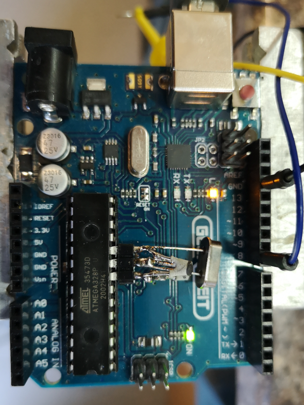
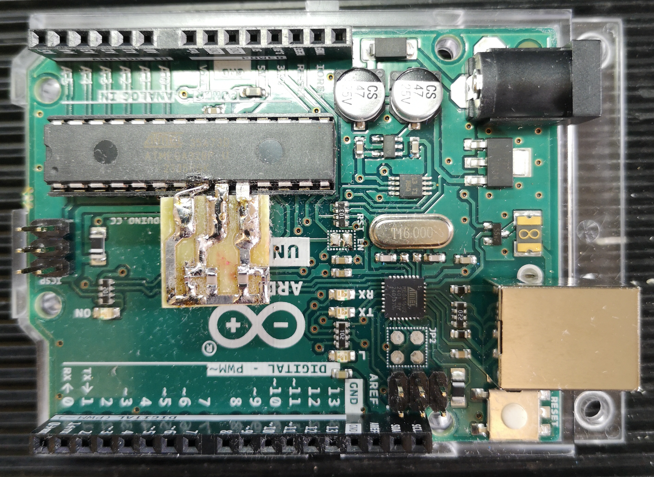
Rather than hack the UNO board, I eased the processor out of its socket and bent pins 8 (ground),9 (xtal) and 10 (xtal) out horizontally and plugged the processor back into its socket. Using a three pin socket pushed onto the pins as a mounting, I assembled the crystal across pins 9 and 10 and two shunt capacitors (approx 33pF) to the ground pin. The crystal came from RS Components (#8149440) and was a 30ppm spec. This socket mounted lash up was then pushed into place on the floating process legs – very healthy, no damage done to the processor or the board. Here is the ugly mess.
Switched on. It worked.
Suddenly all my test source readings took on a very stable repeatability and the readings were very close to what I expected. The GPS referenced 1s pulse was reading 0.999936 and my SY9600 was reading 0.999958. It looked like my new crystal reference must be slightly off frequency but a tweak of the shunt capacitor values will fix this. I think the SY9600 has a 10MHz TCXO so it should be good but I think I tend to believe the GPS pulse as being more accurately delivering a 1Hz rate.
The experts will tell me I should be adjusting the fusible links but I am inclined to stick with what I have got, it is working.
The result is I now have an ability to measure the pendulum rate and from this I can derive an advance and retard flag.
I am currently designing the front end circuitry as shown above into a PCB ‘shield’ to plug into the UNO. This will take the sensor input and give a slow or fast command pin output. More on this and general progress to follow.
Update (30/9/2024)
I changed the two crystal oscillator shunt capacitors to be a 22pFSMD in parallel with 1p8 caps when using the RS crystal as mentioned. Below is a suitable layout for the crystal and shunt caps. There are positions for two caps on each leg of the crystal. 15pF in parallel with 6.8pF would also work. I checked the frequency was close using a GPS derived 1pps signal feeding pin 8 on the UNO while running the frequency.h demo sketch.
The board can be connected using the mounting holes or it can be cropped and the residual pcb tracks used as direct connections using pins 10 and 9 both of which are bent out from the IC body. Pin 8 was left plugged into the IC socket and bridged and soldered across with a wire clipping to the crystal board. The crystal mounts on the rear. The board is so simple you could mill it on single sided copper clad with a burr in a Dremel.
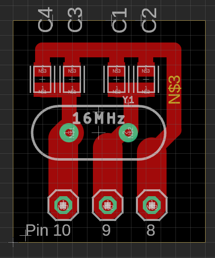
The picture below shows the first milled version in place on the UNO. The layout above is a later tweaked version to better match the pcb pads to pins 9 and 10.
Links to similar or related post are listed below : –
- Arduino Processor Reference Clock Accuracy
- 3D Printed Length Gauge for In Barrel Mainsprings
- The “Modern Clock” by Goodrich
- Microset Timer interface using Fusion 360 3D model with Fusion Electrical
- Clock adjuster rod for measuring spring and fusee drive power
- Update notes on modifications to the Devon Sea Clock
- A church clock problem and lockdown timekeeping
- Repairs to an ancient Thwaites clock completed
- Further 3D printed soft jaws for the Thwaites clock escape wheel
- Vice soft jaws and then soft soft vice jaws