Keeping the village clock going
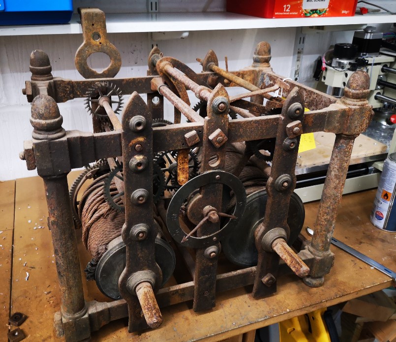
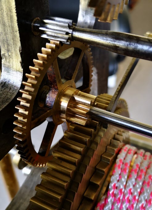
From previous posts you will be aware that I am regarded as ‘Tech Support’ for the local church clock. The clock is a Cooke of York design dated from 1869. It has been running very well over the past months until a few days ago when ….twang … one strand of the strike wire rope gave way and twirled back up the rope and got wedged in the strike mechanism. The going train continued to keep time and display on the dials but no bell strikes. An eerie silence fell over the village.
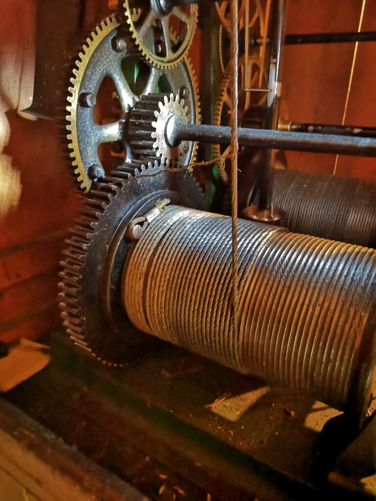
The errant stand of wire was easily cleared but on further inspection the strike weight rope looked to be in a dangerous condition. I resolved to replace the rope and while doing this I would also replace the cable on the going train.
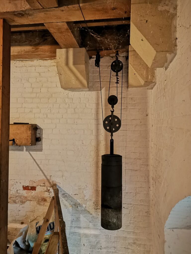
The strike chain had jammed with the weight almost at the top so this needed to be gently let down to floor level.
New fibre cored 6 x 19 galvanised wire rope was ordered. The strike train had 6mm diameter and the going train 5mm and both needed around 30m of cable. The chosen supplier was RAMS Lifting Gear in London and they agreed to put a 20mm diameter soft loop at one end of each cable. This would loop over a button on each of the two barrels to anchor the cable. RAMS delivered the cables very quickly.
Given the social distancing restrictions in place, my normal assistants were not available to help. Instead I persuaded my wife to climb the bell tower with me to assist with the cable changes. It is a bit intimidating to ascend up the two ladders for the first time but she overcame her nerves and after a few up and downs became quite at home with the surroundings.
The new cables were unreeled and laid out down the stairs from the tower into the church so they could take their own path and not twist. We had decided to use the existing cables to pull through the new ones. This meant the soft loops and the associated crimps had to be pulled through each pulley. This was tight on a couple of them but we managed.
With the cables pulled through and into the clock cabinet we then pulled off the old cable from the drums and ran on the new ones. Inspecting the old cables revealed that they were not in the best condition and could have been an accident waiting to happen had they snapped clean through. There is no clock record to indicate when they were last changed.
The clock was soon up and running with its new shiny cables and normality was restored in the village and surrounds.
We received a number of appreciative comments from the villagers for getting the clock up and running again so quickly. Considering these comments suggested that perhaps the chimes of the clock had taken on a new meaning in COVID lockdown. Time precision had recalibrated. Watches and clocks in and around the home had ceased to be the reference in the slow world of lockdown. Nowhere to go or to be, meant watches lay on bedside tables unworn and unwanted. Instead people had moved from watching minutes to referencing life by hours. The village clock now subconsciously marked the passage of time with its hourly chimes. Everything in between had become a slowed down lifestyle. When to come or go into the garden or to the shops, when to think about a meal – all now seemed more likely to be triggered by the hourly chimes of the village clock.
Which is probably how life was in 1869 when the clock first broadcast its notes over the village.
Did we perhaps lose something somewhere along the way ?
Similar or related subjects : –
- Arduino Processor Reference Clock Accuracy
- 3D Printed Length Gauge for In Barrel Mainsprings
- The “Modern Clock” by Goodrich
- Microset Timer interface using Fusion 360 3D model with Fusion Electrical
- Clock adjuster rod for measuring spring and fusee drive power
- Update notes on modifications to the Devon Sea Clock
- A church clock problem and lockdown timekeeping
- Repairs to an ancient Thwaites clock completed
- Further 3D printed soft jaws for the Thwaites clock escape wheel
- Vice soft jaws and then soft soft vice jaws