Another JSN Job ?
You know how I keep on going on about how solutions to problems are often solved by coming at them from different and often unconventional directions, by utilising and marrying available resources ? It was a philosophy that I encouraged in my team while running my business and it has carried over into my way of working in retirement. A recent job brought his home to me.
A client had a very old clock that had had a new barrel wheel made and fitted but the clock would not run for more than a few minutes. There appeared to be an incompatibility either between the modulus of the new wheel and its mating pinion or the shape of the original pinion did not match the shape of the new wheel.
If you spun the barrel wheel you could feel the resistance build up as the synchronisation between the two profiles drifted out. Adding extra weight to the barrel helped but did not solve the problem.
So what to do ?
The barrel wheel was serious engineering and I did not fancy making a new one. The existing mating pinion was a seven leaf format and its leaves were what you might call pear drop shaped rather than the expected profile. The pinion arbor had a 72 tooth wheel driving the next part of the clock train but we did have a spare one of these to hand from the minute dial.
Calculations from the geometry of the barrel wheel resulted in a modulus figure of 1.86. A rather large value and not one that conventional cutters are readily available for. The pinion was perhaps something that could be drawn in Fusion 360 and then made on my Tormach CNC PCNC440 milling machine. The only snag was that the profile needed on the pinion would likely be weird and the world’s supply of brass could diminish rapidly while getting the profile correct.
Using Gearwheel Designer I created what would be the expected profile for a 7 leaf pinion with a modulus of 1.86. This was exported as a DXF line drawing into Fusion 360. This outline was extruded in Fusion into a 3D design and a boss was added to mount the 72 tooth wheel.
The design was 3D printed on my Sindoh 3DWOX printer and was mounted on a 6mm silver steel arbor. I added a driving disc that interlocked with the printed pinion and the crossings on the wheel to drive the assembly. Surprise surprise it didn’t run but it did mirror the regular pattern of stiffness of the original pinion.
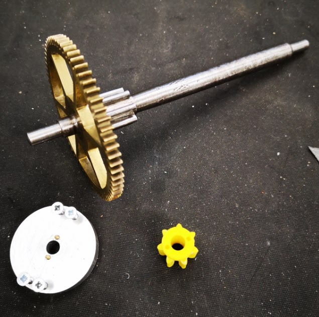
I now had the test bed for quickly making and testing different pinion profiles. There followed a number of hours watching the engagement progression of the profile of the pinion into the barrel wheel and then trying to conceive a profile for the pinion that might run.
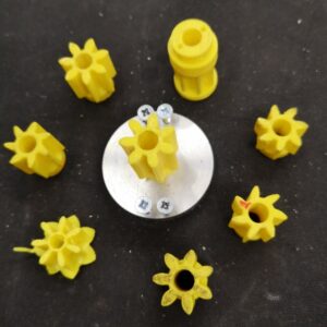
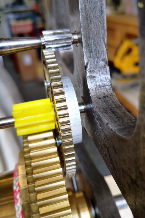
Fusion 360 made this process so easy and round 10 printed test profiles later I had success with a clock that now ran. The driving weight on the barrel was around 11kg and it looked to be worthwhile wasting some brass making a ‘proper’ one.
I took the 3D design and produced CAM code in Fusion. This would cut the profile ‘on end’ using an adaptive first cut with a 4mm end mill followed by rest machining the remaining material with a 2mm end mill.
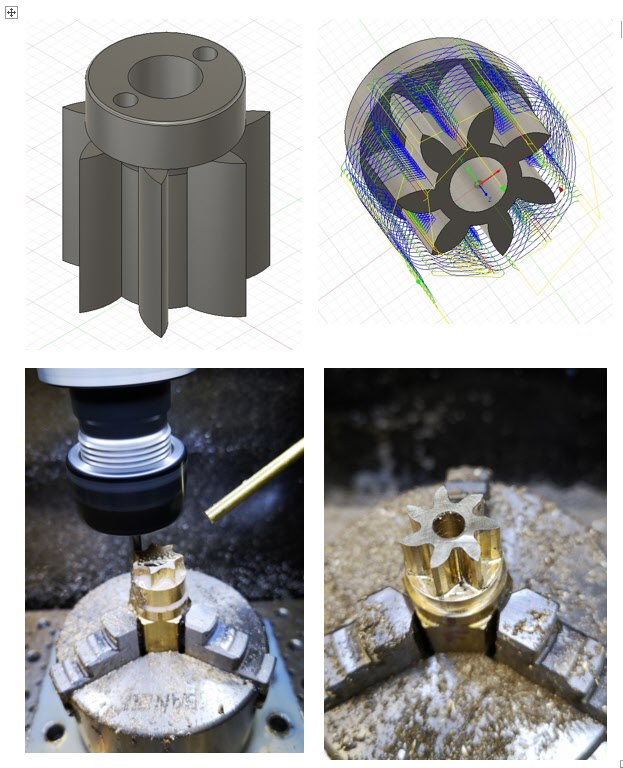
The resulting brass pinion was mounted on the arbor and the clock ran with a strong beat. As expected the brass pinion gave less surface to surface resistance than the 3D printed part and the barrel driving weight was now able to be reduced down to 6.25kg.
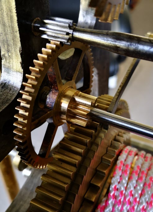
I ran my Microset Timer on the clock overnight and had a first off timing error of 5 minutes per day which was fixable with a pendulum tweak. The movement had an instability of a few seconds per day which was quite astonishing.
The conclusion of the experience is that at first glance this seemed like a conventional pinion cutting exercise …. but M1.86 cutters are not readily available. If a cutter could have been found at less than a King’s Ransom it is likely that the resulting conventional profile would have been wrong to match the barrel wheel.
The alternative route that was taken of Gearwheel Designer to Fusion to 3D print to Fusion CAM to CNC machining solved the problem albeit with a final weird profile. The purists and traditionalists will groan. There will be a gnashing of teeth and a pulling out of hair.
Does it really matter if the result is new life for what could have become a heap of scrap metal ?
Similar or related subjects : –
- Arduino Processor Reference Clock Accuracy
- 3D Printed Length Gauge for In Barrel Mainsprings
- The “Modern Clock” by Goodrich
- Microset Timer interface using Fusion 360 3D model with Fusion Electrical
- Clock adjuster rod for measuring spring and fusee drive power
- Update notes on modifications to the Devon Sea Clock
- A church clock problem and lockdown timekeeping
- Repairs to an ancient Thwaites clock completed
- Further 3D printed soft jaws for the Thwaites clock escape wheel
- Vice soft jaws and then soft soft vice jaws

