I had a contact through my blog from a gentleman who had inherited a Burgess Bandsaw. I have published various support details for the BK3 so he was curious about the model in his possession and he sent me some pictures as shown below.
I have never seen this model before. The BK1 through BK3 all have a belt drive from the motor but this one has a chain drive. The shape of the housing is much more curved and both the blade wheels look to be cast and perforated rather than being plastic. It is clearly a very early model, probably before the design went through a manufacturing cost reduction.
The manufacturers plate suggests this is Serial #225.
If anyone knows the likely history of this version I would be interested to know more details.
Links to similar or related post are listed below : –
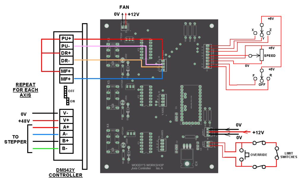
Some while ago I described how I had fitted stepper motors to my Myford VMB milling machine. It was not the intention to convert the mill to CNC but simply to give my arms a rest winding handles back and forth. This was particularly so with the Z axis. The secondary advantage is that the motor driven movement leaves a much smoother finish than my hit and miss erratic winding of the hand wheels.
The design is Arduino based and allows selection of a single axis at a time with variable speed control in forward or reverse direction together with the option to fit limit switches/emergency stop facilities. The PCB, with appropriate stepper hardware, could be applied to any other machine needing motorised movement.
Following some recent publicity of the conversion, I received a number of requests for the unpopulated printed circuit board. I now have a few of these left in stock if anyone is feeling adventurous. Here is a view of the external connections needed.
This conversion started off as a ‘I wonder if I can’ and is now probably one of my favourite projects in terms of its impact on my day to day use of the VMB.
Links to similar or related post are listed below : –
While coming to the end of a running session of my 5″ loco at the club raised level track I suddenly realised the axle pump was not making its normal rattling noise. Water level was likely very low and there appeared very little in the glass sight gauge. My state of panic endured until I reached the filler hose.
On returning home to the workshop I resolved to try to make this alarm situation more readily visible. The common solution is to add a second sight glass feeding from the water tank and visible in the ‘cab’. My engine did not have a great deal of room for this addition.
Sacrilegiously I began to consider an electronic solution which probably wouldn’t make me popular with the mechanical diehards but the challenge appealed.
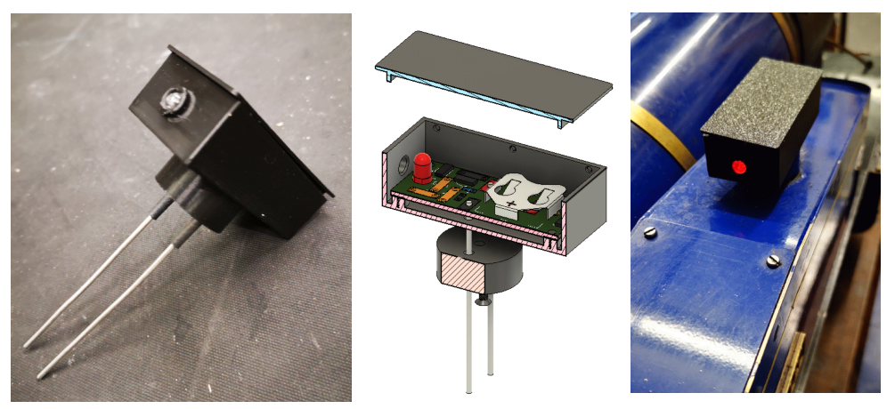
The electronic solution turned out to be a multi faceted activity. An initial bird’s nest lash up was followed by a PCB designed in Fusion 360 Electrical. The PCB was milled on my vacuum table fitted to the Tormach 440 with the Gerber and Epsilon files converted to GCode using FlatCAM. Having completed the PCB board this led to a customised enclosure designed in Fusion 360 and 3D printed in the Qidi X Smart 3.
The circuit is a NPN transistor that is turned on by water conduction between two sensor probes which in turn drives a second NPN to illuminate a flashing LED. The module is powered by a CR2025 button cell.
The enclosure consists of three parts, the base, a snap on lid and a round boss that matches the diameter of the water filling hole on the engine side tank. The two water sensing probes are made from 16 swg wire protruding from the boss.
The round boss is held in place with a M2.5 countersink screw and could be dimensioned to suit different sized filler holes. Having it as a separately printed item is also useful in that it allows the enclosure base to be 3D printed without support.
Here is are some views of the completed assembly.
It seems to work quite well and is surprising sensitive down to the last few millimetres of the probe rods. Time will tell.
If you want more details then please send me a message.
Links to similar or related post are listed below : –
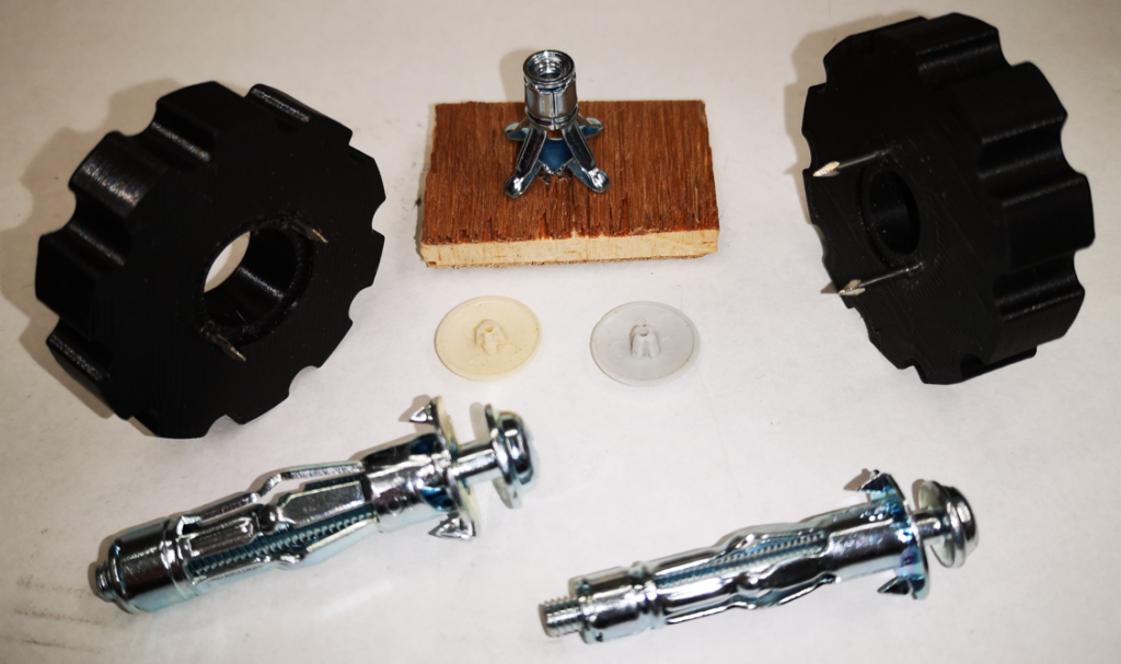
In my experience there is only one fixing style that works with plasterboard lined walls. These are shown in the image below and are supplied in various mounting thread sizes. The image below shows the 4mm and 5mm versions. Also shown is an example of how they expand out when you clamp them inside the cavity behind the plasterboard. Note that while intended for dry lined walls, these can also be used on thin walled surface such as a modern ‘hollow’ door (good for bathroom towel hooks). The fasteners are available in various lengths to suit the mounting surface thickness.
In use you drill the appropriate clearance hole for the body (6.8mm for the 4mm version and 8.8mm for the 5mm version) and push the fastener into the hole so it is flush with the outer surface of the plasterboard. You tighten the screw to cause the ‘wings’ to expand in the cavity.
There are a few issues with this. To cause the expansion process to start you have to apply a lot of pressure downwards on the screw head. Once you feel the screw beginning to turn easier you are on the way to crushing the wings against the wall inside surface. The next test is judging when you have reached optimum expansion of the wings. This comes with experience. The screw rotation will go from relatively easy to increased pressure.
When used on plasterboard the two triangular prongs on the fastener are supposed to grab into the plasterboard surface and stop the fastener rotating as you tighten the screw to initiate the wing expansion. My experience is that you need to apply heavy downward pressure on the screw head to stop the prongs just rotating free and cutting a nice circular vee groove in the plasterboard surface. This is slightly less likely to happen if you are fitting one to a hardboard surface such as a hollow door as the hardboard will give greater resistance to the rotation.
This tightening process can be helped if you put a washer under the screw head with some grease. This eases the possibility of the whole fixing rotating.
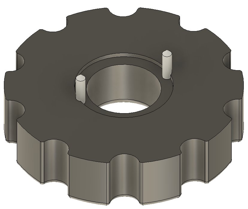
You can buy a tool for mounting these fixings. My version is a 3D printed double pronged restraining jig. So far I have created two sizes, one for 4mm and one for 5mm threads. It is simply a disc with two 1.6mm panel pins embedded in it that mate with the notches in the fitting. The tool is offered up over the fastener with the pins in the V grooves and then pushed home into the plasterboard. The pins embed deeper in the wall surface than the prongs on the fastener and stop it rotating.
A couple of other comments. Once you have the fastening in place on the wall the screw thread will likely be longer than you will need to hold the object being fastened to the wall. You can therefore substitute a shorter screw as needed so long as it is long enough to mate with the fastener thread. You can also change the screw head style. When fitting curtain battens I use a number of these fittings along the batten length and replace the dome head screws with countersink heads into which I fix the commercially available small plastic star head covers (see below).
Here is an image of the fasteners, the two jigs sizes I use, a view from the rear of how a fastener expands in the cavity and the small coloured plastic covers that can be used to cover countersink screws.
Depending on the technique that has been used to fix the plasterboard, you can sometimes have a reduced depth of cavity for the fixing. This can be overcome by drilling the mounting hole for the fastening not just through the plasterboard but as deep as need to match the fixing’s length into the solid wall behind. This allows you to get the fastener in place and the expansion of the wings will not be inhibited. Clearly this is not so easy with a steel lintel behind the plasterboard …..
The STL files for the two sizes can be downloaded on the link below. I used PLA with a 4 perimeter print and 0.25mm layer depth. Once printed, clean out the two panel pin mounting holes with a 1.6mm drill. Cut the panel pins to around 6-8mm length and push home into the drilled holes. The small counterbore on the print surface will match the fastener flange but not to full depth so there is a pressure exerted from the jig as you push it against the wall.
I have a Record #34 vice. It has a seriously chunky tommy bar. If you accidently let this drop with a finger in the way you are heading for expletives and a large blood blister.
The fix is to force two O rings over the end stops to act as buffer protection. Apart from lowering your blood pressure and saving your stock of BandAids it reduces the clunk when the bar drops with or without your skin in the way.
Links to similar or related post are listed below : –