Three axis stepper controller PCB in stock

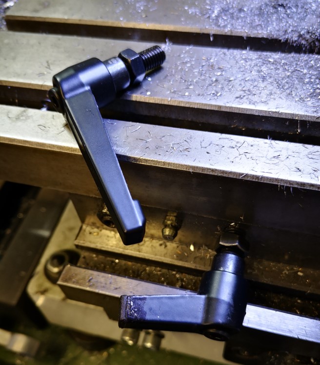
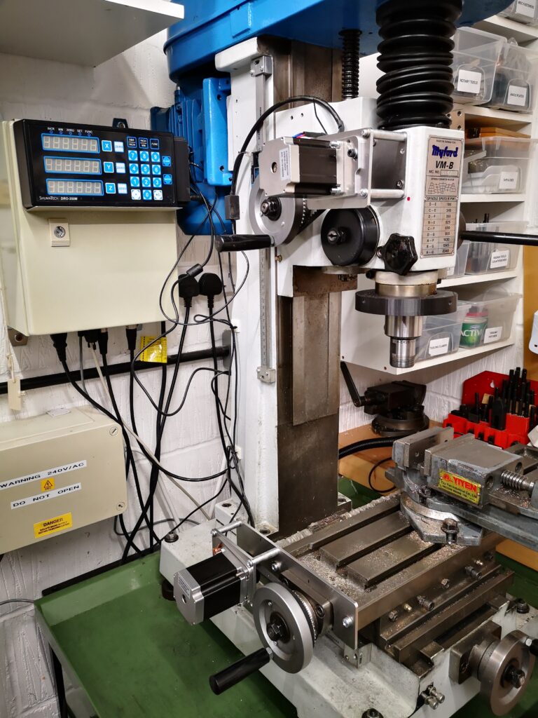
Some while ago I described how I had fitted stepper motors to my Myford VMB milling machine. It was not the intention to convert the mill to CNC but simply to give my arms a rest winding handles back and forth. This was particularly so with the Z axis. The secondary advantage is that the motor driven movement leaves a much smoother finish than my hit and miss erratic winding of the hand wheels.

The design is Arduino based and allows selection of a single axis at a time with variable speed control in forward or reverse direction together with the option to fit limit switches/emergency stop facilities. The PCB, with appropriate stepper hardware, could be applied to any other machine needing motorised movement.

You can read the full article here.

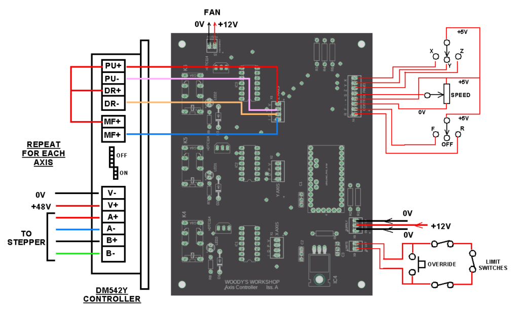
Following some recent publicity of the conversion, I received a number of requests for the unpopulated printed circuit board. I now have a few of these left in stock if anyone is feeling adventurous. Here is a view of the external connections needed.

This conversion started off as a ‘I wonder if I can’ and is now probably one of my favourite projects in terms of its impact on my day to day use of the VMB.

Links to similar or related post are listed below : –

Truncated Lock Levers

Restricted space modified lock levers

Each of the axis locks on my VMB mill uses two M8 cap head screws in association with a lock nut. This works OK if the hex driver is in reach …. but it never seemed to be …. so I decided to remove the cap head screws and fit lock levers instead. Lock levers come in male and female format and various thread sizes. The M8 versions all have 40 to 50mm long lever arms. This length doesn’t work comfortably in the space constraints on the VMB X and Y axis but is fine for the Z axis. Similarly I also had to reduce the length of the lever thread.

The obvious solution was to cut down the length of the lever arms. The trouble with this was the raw open end of the arm looked naff and did not sit easily with my usual perfectionist approach. The solution via Fusion 360 was to create some 3D printed end caps which I then bonded in place with Araldite. This finished the job properly.

Fusion 360 modelled end cap for the shortened lock lever arm open end

The Fusion 360 3D modelled end cap printed in under 4 minutes with a further 5 minutes for the Araldite to cure. I now have a much more elegant looking solution.

Full length lock lever and the truncated version with 3D printed end cap mounted on my VMB mill

All of which has led to a rethink the lock levers on my Quorn tool grinder. I get in a real mess with these clashing with each other. Where did I put the Araldite ? …..

Links to similar or related post are listed below : –

Adding stepper motors to a Myford VMB manual milling machine

Myford VMB Manual Mill Conversion to Stepper Motor control

After many years of winding the Z axis up and down on my Myford VMB I have finally got around to fitting motor control and it is a joy to use.   I am however suffering from muscle wastage as a result.

stepper motor control of a VMB manual milling machine
A general view of the stepper motor control conversion of a VMB manual milling machine. Only the X and Z axis are completed so far. The control box is on the wall behind the mill and has the Shumatech DRO control panel mounted on the front panel.

I have done a write up for those who might want to also enjoy a less taxing movement of X, Y or Z axis on their manual milling machine.  Click on the link below to download as a pdf.

 Fitting XYZ motor feeds to Myford VMB v4

Similar or related subjects : –

Verified by ExactMetrics