Fogbuster update on my Myford Super 7 lathe

Plan B Fogbuster Mounting on the Myford lathe

Of late there has been a long thread running about Fogbuster use on the MEW forum.   This set me thinking.  The forum debate centred on whether mist lubricant or flood coolant was more or less healthy.   For hobbyists the consensus seemed to favour the mist coolant.  This was with the proviso that the jet and coolant mix is carefully balanced.  An interesting point was made about ensuring the air stream was pointing away from the operator to avoid blowback.  If all is good you should not be able to smell the lubricant.   (N.B. I use QualiChem Xtreme Cut 250C at around 8% dilution).

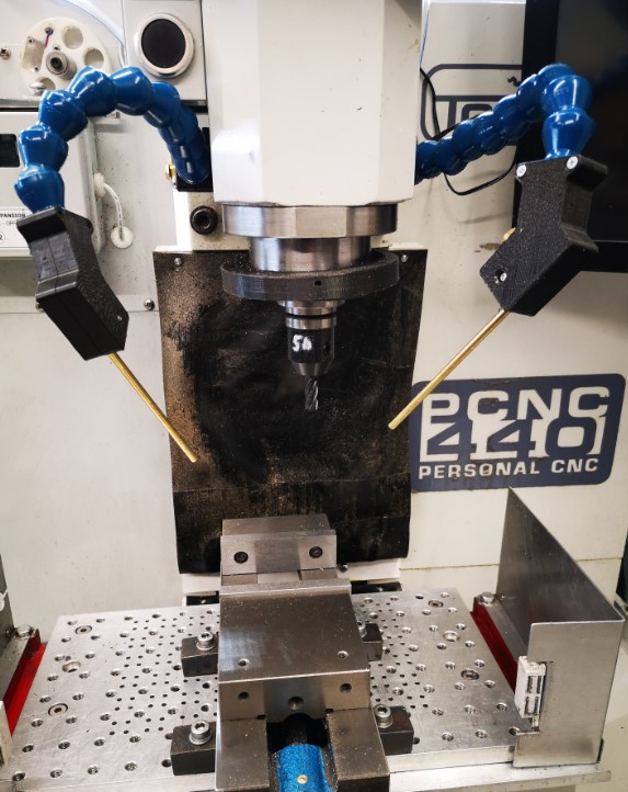
The installation on my Tormach PCNC440 is fine with respect to blowback at the operator.  Both nozzles are on flexible mountings and can be easily directed towards the back of the mill.  (See prior post).

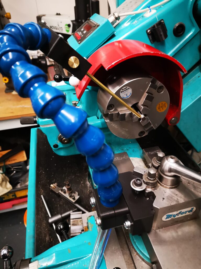
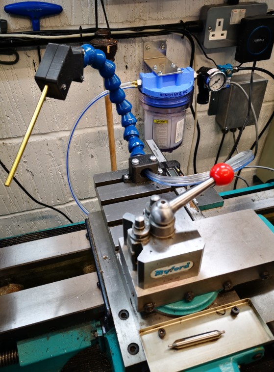
My installation just completed on my Myford Super 7 is not quite so perfect.   I was using a T slot at the back of the saddle as the nozzle mounting.  This meant the nozzle was playing on the back of the workpiece and towards the operator.  Perhaps with hindsight not the most healthy option.   OK so I don’t use lubricant on the lathe that much as most of my work is brass and aluminium so maybe less of a critical issue.   Because of the infrequent use I wanted the Fogbuster to be quickly demountable until the next steel job comes along, hence the T slot idea.

I have a Myford Quick Change Toolpost fitted on the Super 7 which has two tool holder positions at right angles to each other.  It struck me that the Fogbuster could be mounted in the QCTP unused slot.   This would allow the air jet and lubricant to point forwards towards the workpiece.  Normally I would have the empty slot on the far side face so a boring bar can be dropped into place.   By rotating the QCTP through 180 degrees the spare slot would sit nearest the operator and be ideal for the Fogbuster.  

I didn’t really want to dedicate a steel tool holder to the Fogbuster so I created a 3D printed version.   This picked up on the prior mounting holes I had modelled in the flexible clamp.

I needed to make sure my 3D printed profile was a good fit in the QCTP so after fully modelling it I moved the time line in Fusion back to the profile extrude and reduced this from 26mm to 5mm and ran a test print on just a 5mm depth version.   This allowed a quick print to be done which gave me feedback to do some minor edits.   The timeline then was dragged fully forward and a full size print run.   Try doing that as easily and quickly in steel ?

The pseudo toolholder 3D print ran in around 90 minutes and looked and fitted well.   To finish off, I turned up a small clamping button to match the normal clamping and height adjustment screw on the QCTP.

Hey presto a new Fogbuster forward facing mounting ready to go.
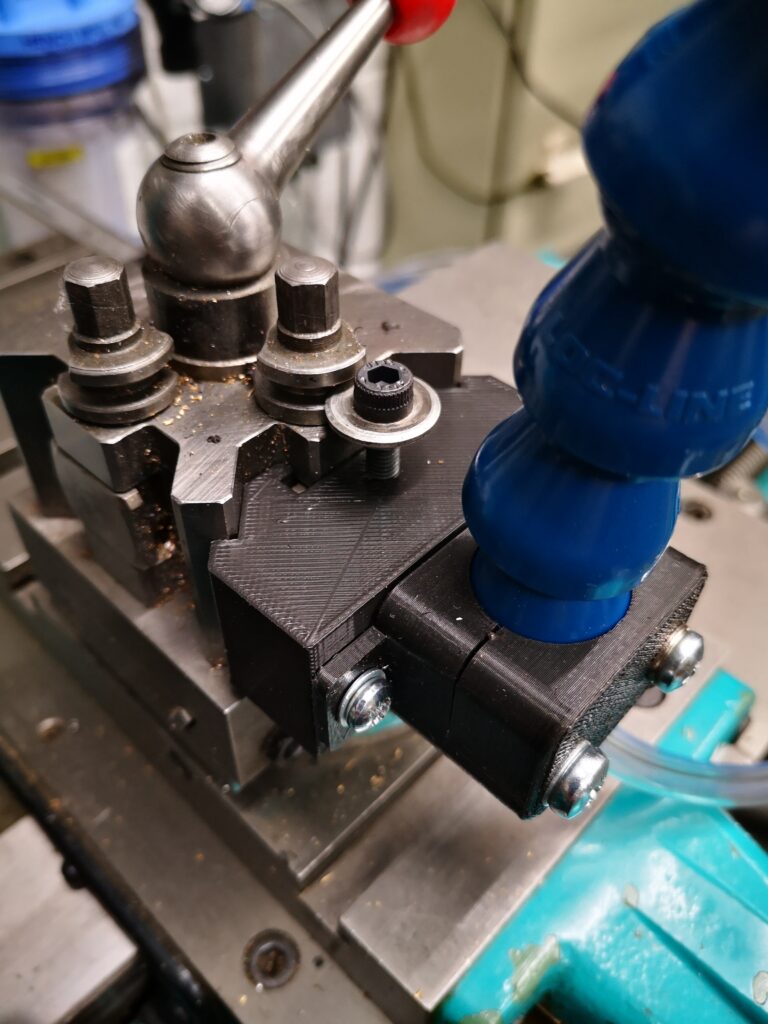
Close up of Fogbuster mounting using the Myford QCTP
Fogbuster mounting using the Myford QCTP
Overview of Fogbuster mounting on a Myford QCTP

Similar or related subjects : –

Fogbuster update prompted by Clough42 and other projects

Fogbusters Everywhere

Apart from working on the Thwaites clock parts, I have also done an upgrade to the mounting of my Fogbuster coolant nozzle installation on my Tormach 440.  This was triggered after viewing and being impressed by Clough42’s idea.   The Fogbuster is a great way to clear swarf and apply coolant.  The Fogbuster is normally supplied with a magnetic mounting arm but James’ modification uses LocLine gooseneck components to provide a much more flexible ‘aiming’ capability.

Something to be aware of – James recommends a download from GrabCAD for the 3D files of the two halves of the nozzle holder.   These had been uploaded by contributor Br BRB.  These were apparently publicly available via GrabCAD.  James slightly modified these and was offering them as a free download from his Thingiverse folder.  He has since had to remove them for download due to commercial issues.   BrBRB has also removed the original files from GrabCAD and is seeking to sell these as finished items.  I was lucky to have downloaded the files before the politics cropped up.  I  still have the downloads.

James also advocates fitting a second identical nozzle to the Fogbuster to avoid coolant and air shadowing.   I contacted Fogbuster in California and a very helpful lady called Rachel organised an upgrade kit to provide a second feed from my existing coolant reservoir. 

Dual Fogbuster coolant nozzles on Tormach PCNC440
Dual Fogbuster coolant nozzles on Tormach PCNC440 using Clough 42 flexible nozzle idea

It turned out Rachel was from Bristol UK so it is a small world and we had a good chat.   I have fitted both nozzles to the Tormach.  With a pressure of around 10 to 15 psi, the reservoir feeds both nozzles very well and is a huge improvement in use. 

As I was facing a shipping charge from the US I figured I might as well top up the package so I have also splashed out on a baby version of the Fogbuster to fit to my Myford lathe.  This uses the same idea but with slightly different mounting that fits into the T Slot on the Myford saddle.   I already had the 3D model of the T Slot strip from the ‘bits tray’ installation.

UPDATE : – I went to a Plan B on the lathe mounting – see later post

Baby Fogbuster mounted on Myford Super 7 saddle
Baby Fogbuster mounted on my Myford Super 7 saddle based on the Clough 42 flexi nozzle idea

Another pair of incremental asset improvements successfully installed.  I suppose I had better get on and make something now. 

Back to ‘the clock’ …

UPDATE 2 : – The 3D printed ball joint kept working lose on both the milling machine fogbuster mouunts.  The more I tightened the screws to grip it tighter, the more the 3D components began to crack and give way.   The solution was to fit brass inserts into the 3D prints.  Problem solved.  Incidentally there is a good review of such inserts on CNC Kitchen.

Similar or related subjects : –

Tormach PCNC440 Fogbuster and Manual Oiler Service

Back from after a few weeks in France and back in the workshop.

Every now and then there is a project that is on the go and you can’t sit down and focus on it.  It is a sort of mechanical procrastination.   A reluctance to put the first pencil mark on the paper.   You then suddenly find all sorts of other things that you kid yourself are more important / higher priority and you get distracted.   You know that job will still be there but maybe tomorrow, not   today.   You suddenly develop a clear conscience about doing something else while you do some background thinking ….

This particular day started off by cleaning down the accumulated swarf (chips) in the 440 tray.  Really important job.  This led to a check behind the various 440 slideway bellows to see that all was well with the oiling mechanism on the slideways and the ballscrews.   X and Y were fine but Z was dry.  Not good news.   

The 440 is supplied with a manual oiler as standard.   This is a reservoir of oil and a pump/plunger which you pull out and release to initiate a slow pressure to the oil distribution pipes. 

Tormach manual oiler reservoir
View of the manual oiler mounted on the Tormach 440

 I checked the plunger and it didn’t feel like it was applying much pressure.   This is not the first time I have experienced this problem.   If I pumped a few times it felt better so something should have been happening at the oiling points on the Z.   I disconnected each of these where I could  and sure enough if I pumped hard enough some oil dribbled out but not with much pressure.   Something probably not right with the plunger ?

Squeezing round the back of the mill I removed the top of the reservoir (4 retaining screws), disconnected the oil pipe union and lifted the plunger clear.  The reservoir can be left in place sitting on the mounting bracket. 

There is a large end cap at the union end of the plunger cylinder which I removed and sure enough I could see a mangled O ring.   To get the plunger out you have to be a bit brutal.   You pull the T handle plunger back out of its housing against its spring using the handle as shown above and then grip the shaft with pliers so you can then twist the handle off.   What you don’t do then is suddenly release the pliers grip or the plunger will go into low Earth orbit under the pressure of its spring …

Having disassembled the plunger it was obvious that the O ring had failed quite badly.   Tormach support do not offer spares as the oiler is a third party item.  They do not know what size the O ring should be.   Checking in my box of miscellaneous O rings it looked like a 9mm ID, 3mm thickness part would do the trick.   Smearing the O ring with DC4 silicon grease allowed easy re-assembly into the piston bore and then back onto the 440.  I now had lots of pressure and oil was apparent trickling down the Z slideways and ball screws.  Job done.   No pumping needed, just one pull out of the piston handle was generating a slow release of oil to the key areas.

The job I should have been doing was still sat on the bench glaring at me but psychologically I was doing something more important.

Next problem was the Fogbuster air activation valve.  Under CNC control this reliably switched on but sometimes would not switch off when commanded to.  There are various forum discussions on this problem and many contributors just replace the solenoid valve with a different version.   Forum chat also recommended that electrical transient snubbers are fitted across various inductive loads in the Tormach control unit.   I had some of these in my stock box (Tormach offer a kit for this).   They are simply a series resistor and capacitor in an epoxy block.   They are fitted across any inductive device to suppress switching transients.   I dived into the control box and fitted one across the controller relay coil that switches the Fogbuster ON and OFF and another one across the outlet from the control box feeding the Fogbuster solenoid coil.   See picture below.

snubber inside tormach cabinet
Snubber across Fogbuster activation relay coil.  There is a second snubber fitted to the lower LHS contact which activates the air solenoid.   The other end of this snubber goes to the any ‘100’ connection which is mains neutral.

The problem seemed to be improved but still occasionally the solenoid did not switch OFF.

The Fogbuster solenoid has a clear housing over the activation coil connections and there is a LED inside this that comes on when the Fogbuster is switched on.   

Fogbuster activation solenoid
Fogbuster solenoid assembly showing the connection clear housing which plugs into the solenoid coil which in turn sits over the activating plunger assembly.  There is a screw in the LHS to release the electrical connection and the nut on the top releases the coil to reveal the plunger housing.

This connection housing plugs into the coil and the mechanics of the solenoid body and is released with a screw in the end.   Toggling the coolant ON and OFF via the PathPilot user interface I could see the LED responding correctly to the ON and OFF commands but occasionally the solenoid was not closing.   It was therefore not an electrical problem but mechanical.

On top of the solenoid housing is a single large nut which when released allows the solenoid coil to be lifted off.   This leaves two countersink screws which hold the mechanical plunger housing in place and if these are removed the plunger can be gently removed.   Inside the valve is very simple.   A central hole allows the air to pass through and when the solenoid is de-energised a spring forces the solenoid plunger to seal this hole.   I gave everything a thorough blast with compressed air and re-assembled it.   Care is needed re-assembling as there is a tiny O ring seal on the plunger cover.   The solenoid now responds correctly to the PathPilot commands.

Another tick.  Job done.  Warm glow.

That other job is still sat on the bench glaring at me ….

Similar or related subjects : –

Verified by ExactMetrics