A church clock problem and lockdown timekeeping

Keeping the village clock going

From previous posts you will be aware that I am regarded as ‘Tech Support’ for the local church clock.   The clock is a Cooke of York design dated from 1869. It has been running very well over the past months until a few days ago when ….twang … one strand of the strike wire rope gave way and twirled back up the rope and got wedged in the strike mechanism.   The going train continued to keep time and display on the dials but no bell strikes.  An eerie silence fell over the village. 
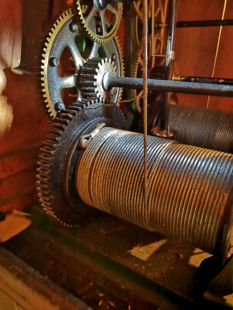
Strike chain drum showing the errant strand in the barrel wheel
Strike chain drum showing the errant strand in the barrel wheel and also the soft eye fastening onto the strike barrel.  The going train barrel can be seen in the background.

The errant stand of wire was easily cleared but on further inspection the strike weight rope looked to be in a dangerous condition.  I resolved to replace the rope and while doing this I would also replace the cable on the going train. 

The strike chain had jammed with the weight almost at the top so this needed to be gently let down to floor level.
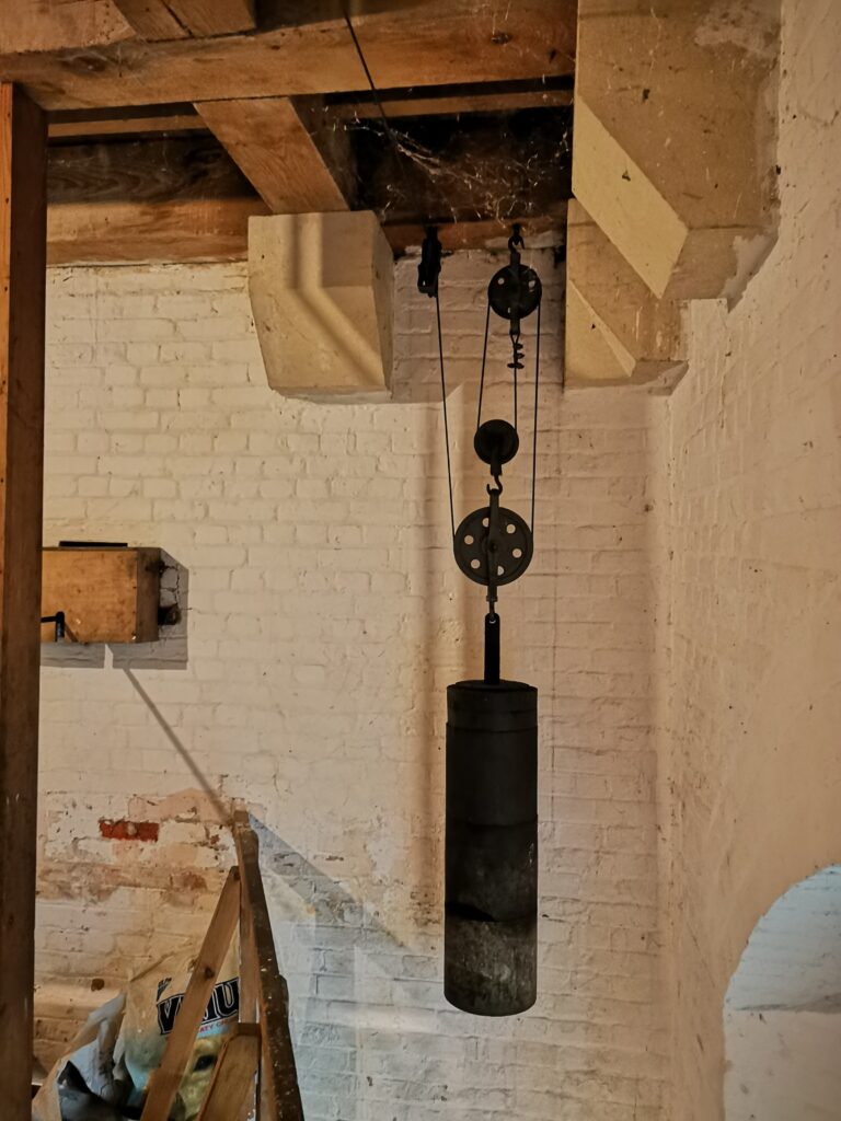
Strike train weight stopped almost at full wind
Strike train weight stopped almost at full wind and needed to be lowered before any work could start on replacing the cable.

New fibre cored 6 x 19 galvanised wire rope was ordered.  The strike train had 6mm diameter and the going train 5mm and both needed around 30m of cable.   The chosen supplier was RAMS Lifting Gear in London and they agreed to put a 20mm diameter soft loop at one end of each cable.   This would loop over a button on each of the two barrels to anchor the cable.   RAMS delivered the cables very quickly.

Given the social distancing restrictions in place, my normal assistants were not available to help.  Instead I persuaded my wife to climb the bell tower with me to assist with the cable changes.   It is a bit intimidating to ascend up the two ladders for the first time but she overcame her nerves and after a few up and downs became quite at home with the surroundings. 

The new cables were unreeled and laid out down the stairs from the tower into the church so they could take their own path and not twist. We had decided to use the existing cables to pull through the new ones.   This meant the soft loops and the associated crimps had to be pulled through each pulley.  This was tight on a couple of them but we managed.   

With the cables pulled through and into the clock cabinet we then pulled off the old cable from the drums and ran on the new ones.  Inspecting the old cables revealed that they were not in the best condition and could have been an accident waiting to happen had they snapped clean through.   There is no clock record to indicate when they were last changed.

The clock was soon up and running with its new shiny cables and normality was restored in the village and surrounds.

We received a number of appreciative comments from the villagers for getting the clock up and running again so quickly.  Considering these comments suggested that perhaps the chimes of the clock had taken on a new meaning in COVID lockdown.   Time precision had recalibrated.   Watches and clocks in and around the home had ceased to be the reference in the slow world of lockdown.  Nowhere to go or to be, meant watches lay on bedside tables unworn and unwanted.  Instead people had moved from watching minutes to referencing life by hours.   The village clock now subconsciously marked the passage of time with its hourly chimes.   Everything in between had become a slowed down lifestyle.   When to come or go into the garden or to the shops, when to think about a meal – all now seemed more likely to be triggered by the hourly chimes of the village clock.

Which is probably how life was in 1869 when the clock first broadcast its notes over the village.   

Did we perhaps lose something somewhere along the way ?

Similar or related subjects : –

The Gravity of the Village Clock

Some time ago I made mention of getting involved with the running of the village clock.   There was an added incentive as this was a Cooke of York movement dating back to 1869.  Anything associated with the  City of York is always of high interest as it was my birth place.  That is except the soccer team but I try not to get drawn into that discussion.

Back to the clock.  Myself and a colleague in the village have been working on the clock to bring it back to time.  We were getting pretty close.   Then it stopped.   Despite a few restarts it refused to run for any length of time.

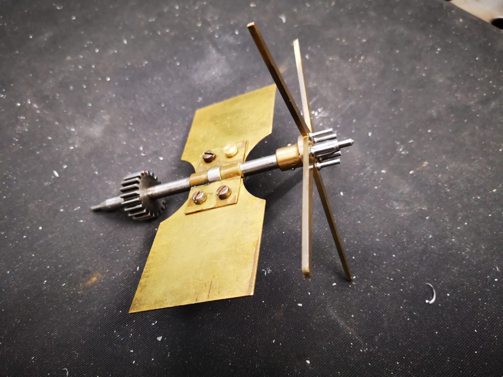
We rolled up our sleeves and gave it a thorough visual inspection.   We were just about to leave it for the day when we spotted that the pins on the pin wheel on the gravity escapement arbor seemed very tight to the arbor supporting bracket.   Closer inspection revealed one pin of the five seemed to be slightly at an angle.  Even closer inspection showed a visible witness mark on the bracket where the pin or pins were rubbing on the bracket.   There was no mechanism to centre the arbor away from the bracket.   

We decided to remove the arbor complete with pin wheel, fly etc.   This was fairly straightforward.  A single screw at the opposite end to the escapement arms could be unfastened and the arbour came free.  Except it wasn’t that easy to unscrew as the screwdriver slot was very narrow.

Having got the arbor assembly back to my workshop I discovered two of the pins were lose, one of them to the point of falling out.   It seemed to have been held in place from coming out any further by the support bracket.   

I marked and numbered the escapement legs and removed each pin in turn, shortened each by 0.5mm, degreased the threads on each pin and its associated mounting hole and then refitted each one with a dab of Loctite to hold them in place. 

Spinning the arbor in my hand I could now see that all pins looked parallel and the length was much more consistent.  Hopefully the pins will now comfortably clear the mounting bracket.

The gravity escapement arbor showing the five escapement legs and the five pins that needed shortening

To make refitting easier I made a small hand tool to fit the slot on the mounting screw and used a hacksaw blade as a pseudo screwdriver blade to more easily turn and tighten the screw.

Since refitting the arbor the clock was running slightly slowly so we removed a penny from the weight tray and it now seems pretty much spot on.

Similar or related subjects : –

Microset Clock Timing Instrument Upgrade

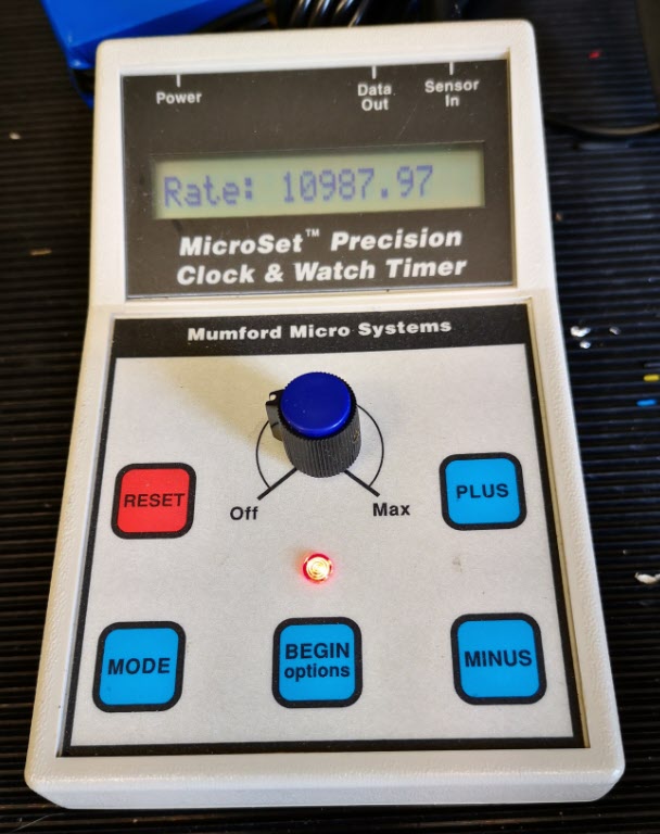
Mumford Microset Clock and Watch Timer

Some while ago I bought a Microset Timer from Bryan Mumford.   This is a lovely device that allows you to monitor all manner of parameters on clocks and watches.   It has an acoustic sensor to listen to the beat of the clock or watch and an optical sensor that creates and detects a beam of light that is chopped by the pendulum.   From these simple accessories all manner of diagnostics can be done on the clock under inspection.   If you want to know more I suggest you log into Bryan’s site.   Bryan also has some videos which you can find on YouTube.   You might also want to download and read a pdf collection of articles written by Chris McKay in the Horological Journal about using the Microset to fault find on Turret Clocks.

Microset Timer from Mumford Micro Systems

The Local Church Clock

If you are a regular reader of this blog you will know that I have got involved with the local church clock which is a Cooke of York movement.   I have been working with a fellow engineer in the village to try to bring the clock to time and we are slowly getting there.   Our last major breakthrough was finding the fly was lose on the gravity escapement arbor.   Since tightening the fly the clock has been much more reliable.

There is a weight tray on the pendulum which has an assortment of coins in it where someone historically has been fine tuning the pendulum swing. Because the clock has been running fast by a few seconds per day we have been slowly removing the coins one by one to bring it closer to time.   I think it is now at a point where we need to monitor it long term with the Microset.

Microset Upgrades

Bryan offers an upgrade to the Microset that allows a temperature sensor to be added to the recorded information.   There will almost certainly be temperature changes in the clock tower so it seemed like a good idea to upgrade with the temperature option.   This was ordered and duly arrived from Bryan and is now fitted.   There is also an upgrade to allow the Microset to record data into internal storage in the Microset rather than depending on having a PC connected.   I would be more comfortable leaving just the Microset in the church pendulum cupboard rather than my portable PC so I also ordered this upgrade.

It took me about an hour to do both upgrades on the Microset.   The memory upgrade involves a chip change inside the device and the temperature monitor needs an additional 3.5mm jack socket fitting and wiring to accept the new temperature sensor.   Neither is a difficult task but clearly need to be done carefully so as not to do any damage to the Microset.   Bryan’s instructions are well written and illustrated.

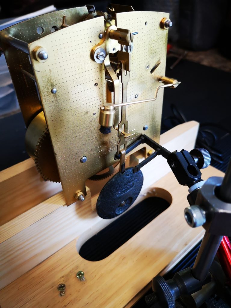
Since the upgrade I have been running the Microset on the bench with a Smith’s clock movement.  (It is actually the one I stripped down, cleaned and rebuilt on my ‘Clocks 1’ course at the BHI).   The new Microset facilities seem to work well and as expected.

Microset optical sensor monitoring a Smith’s clock mechanism

A New Sensor Needed – 1st Attempt

To implement measurements on the church clock the supplied optical sensor as shown in the picture above is not totally ideal.   It has a very narrow gap between the transmit light source and the receiver detector diode which on a turret clock is not  easy to use.   

It is possible to get round this my fitting a cocktail stick or similar to the pendulum bob and using this to break the beam but it is a bit messy. I had picked up a bag of laser diodes and detectors at a local ‘ham’ radio junk sale and I decided these might form the basis of a new sensor which might be more useful to a large pendulum assembly.   Bryan is a really helpful guy and although he does offer a larger laser sensor he was more than happy to help me with the required electronic interface to the Microset.  The one proviso is that the amount of current drained from the Microset 5V power supply must be kept below 30mA.

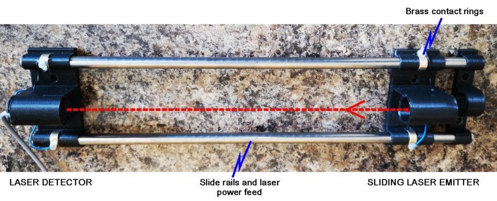
I set to and made the most elegant and over engineered solution for my laser sensor.   This is shown below.   The black mountings were designed in Fusion 360 and 3D printed on the Sindoh 3DWOX.

First ‘elegant’ laser detector for Microset timing instrument

The spacing between the emitter and detector is adjustable by sliding the transmitter along the steel rods.   The power to the laser is also carried down the steel rods.   A small DTC transistor provides the interface to the Microset and the 5V supply provided by the Microset is dropped via two diodes to power the laser.    It works really well ….. but … when I went round to the church to install it I realised I should have checked one or two things first.    The rating nut at the bottom end of the pendulum (used to make course adjustments to the pendulum length) was almost touching the floor of the pendulum cupboard.   My wonderfully elegant laser detector would not fit under the pendulum to monitor the swing.  A serious re-think was needed. The gap was so narrow that at best I will only be able to get a piece of 16 SWG aluminium sheet or PCB underneath the rating nut.

A New Sensor Needed – 2nd Attempt

I did say I had a bag of laser diodes and detectors so a new version would be possible and I could then save the posh one for more public facing activity.

As mentioned above I decided to use PCB as the base board.   This is shown below.

Mk11 Laser Detector Specific to local church clock with little clearance from rating nut to floor

This has the advantage that I can use the copper surface to mill tracking into it to aid the wiring.   The downside is that it is quite flexible and therefore possibly not stable enough to keep the laser aligned with the detector diode.    To resolve this I soldered strips of nickel silver (could have been more PCB) either side of the centre line as shown but leaving a gap for the pendulum swing.

I designed a common holder for the laser and detector diode in Fusion 360 and 3D printed two of these on the Sindoh 3DWOX.

The finished detector assembly still had a tendency to flex so I stuck some old pieces of credit card on the lower surface, one at each end before the mount and a large piece in the middle.   This seemed to cure the problem without adding significantly to the base thickness.

Microset Display

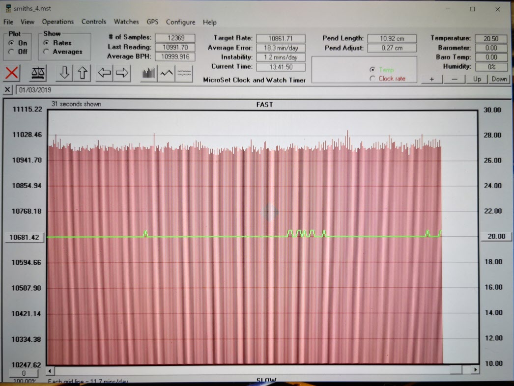
When plugged into the Microset all seemed to work well.   Here is a typical PC display of the Microset data.

Microset Data Display showing the data from a Smiths clock mechanism and also the green line showing the temperature

I now need to get it installed in the church tower.

Similar or related subjects : –

Tower Clocks and Cooke of York

We live in a small village and the local church has a tall spire with a tower clock movement.  Some while ago my friend Dave and I were invited to have look at the workings of the clock which was quite interesting.   The clock is still hand wound twice per week and it does not have any added technology to maintain the time keeping accuracy.  This was some time ago and I thought nothing more of it.

My local village church and clock

Church clock movement by T Cooke of York in the village church

I am a member of the British Horological Institute (BHI) and attend the local meetings once per month.   Earlier this year the subject for the monthly lecture was the Tower Clocks of Cooke of York.   This was particularly poignant for me having spent my early years growing up in the York area.   To my surprise that evening I discovered that the clock here in the village was a Cooke clock.   For those interested the presenter of the talk, Darlah Thomas together with her husband have produced a book on the Cooke family containing a listing and description of the known Cooke clock installations and indeed the optical devices the company produced.  It is a splendid volume worthy of any coffee table collection.

ISBN 978-0-9573733-3-4
Turret Clocks of T Cooke of York by Steve and Darlah Thomas

So back to the story …. the village clock, a Cooke clock and I was living in its shadow.

At the meeting I met David Pawley who spends his life maintaining tower clock movements throughout the south of England.   You can read his website Tower Time here.  I mentioned where I lived and he asked if I would mind helping him with some maintenance on the village clock here in my village.   He had been waiting for the striking mechanism to wind down so the weights were fully dropped and the time was rife to lubricate and check the strike pulley system.   We spent a pleasant morning doing the necessary work and I enjoyed the experience.

During the activity David asked if I could further help him to remove the dials from another tower clock in the local area.   The tower was on a farm estate and of wooden construction.   The woodwork was in need of repair which necessitated a temporary removal of the dials and motion work.   Dave (my friend) and myself duly turned up on the day to help David Pawley and had yet another interesting time working on and removing the items in question.

What impresses me is that these clocks have run for years and years.   The technology available when they were designed and built was basic yet here are movements that keep to seconds accuracy after all these years.

I would not be offending David Pawley if I say he is not young and I would compliment him by saying that he carries an enormous accumulation of knowledge and skills.  One day his knowledge and skills will pass into history and I do not see a new generation filling that gap.   There are a lot of tower clocks in the UK and I can’t see a new generation coming forward to fill the need for maintenance.

Farm estate tower clock

Clock mechanism

Similar or related subjects : –

Verified by ExactMetrics