Workshop resources all coming together like clockwork

Another JSN Job ?

You know how I keep on going on about how solutions to problems are often solved by coming at them from different and often unconventional directions, by utilising and marrying available resources ? It was a philosophy that I encouraged in my team while running my business and it has carried over into my way of working in retirement.   A recent job brought his home to me.

A client had a very old clock that had had a new barrel wheel made and fitted but the clock would not run for more than a few minutes.   There appeared to be an incompatibility either between the modulus of the new wheel and its mating pinion or the shape of the original pinion did not match the shape of the new wheel. 

If you spun the barrel wheel you could feel the resistance build up as the synchronisation between the two profiles drifted out.   Adding extra weight to the barrel helped but did not solve the problem.

So what to do ?   

The barrel wheel was serious engineering and I did not fancy making a new one.   The existing mating pinion was a seven leaf format and its leaves were what you might call pear drop shaped rather than the expected profile.  The pinion arbor had a 72 tooth wheel driving the next part of the clock train but we did have a spare one of these to hand from the minute dial.

Calculations from the geometry of the barrel wheel resulted in a modulus        figure of 1.86.  A rather large value and not one that conventional cutters are readily available for.  The pinion was perhaps something that could be drawn in Fusion 360 and then made on my Tormach CNC PCNC440 milling machine.   The only snag was that the profile needed on the pinion would likely be weird and the world’s supply of brass could diminish rapidly while getting the profile correct.

Using Gearwheel Designer I created what would be the expected profile for a 7 leaf pinion with a modulus of 1.86.  This was exported as a DXF line drawing into Fusion 360.  This outline was extruded in Fusion into a 3D design and a boss was added to mount the 72 tooth wheel. 

The design was 3D printed on my Sindoh 3DWOX printer and was mounted on a 6mm silver steel arbor.   I added a driving disc that interlocked with the printed pinion and the crossings on the wheel to drive the assembly.  Surprise surprise it didn’t run but it did mirror the regular pattern of stiffness of the original pinion. 
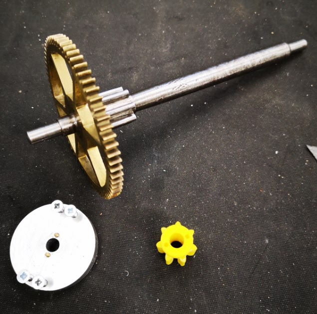
Original arbor , pinion and wheel with the driving disc and a test profile
The original arbor, pinion and wheel together with the driving disc and a 3D printed pinion test profile. The driving disc has screws to lock it to the wheel and two protruding pins to lock into the 3D printed pinion profile under test. The 3D printed profile was a tight pressure fit onto the new 6mm arbor.

I now had the test bed for quickly making and testing different pinion profiles. There followed a number of hours watching the engagement progression of the profile of the pinion into the barrel wheel and then trying to conceive a profile for the pinion that might run. 
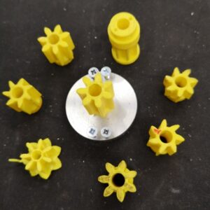
3D printed test profiles
Various trial profiles and the temporary driving disc to engage with the 72 tooth wheel


Test pinion in place on the new arbor
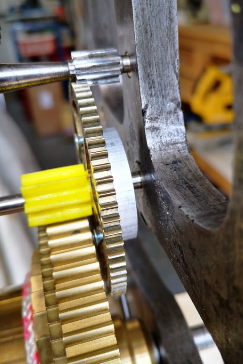
A test pinion in place showing the 72 tooth wheel and the driving disc

Fusion 360 made this process so easy and round 10 printed test profiles later I had success with a clock that now ran.    The driving weight on the barrel was around 11kg and it looked to be worthwhile wasting some brass making a ‘proper’ one. 

I took the 3D design and produced CAM code in Fusion.   This would cut the profile ‘on end’ using an adaptive first cut with a 4mm end mill followed by rest machining the remaining material with a 2mm end mill. 
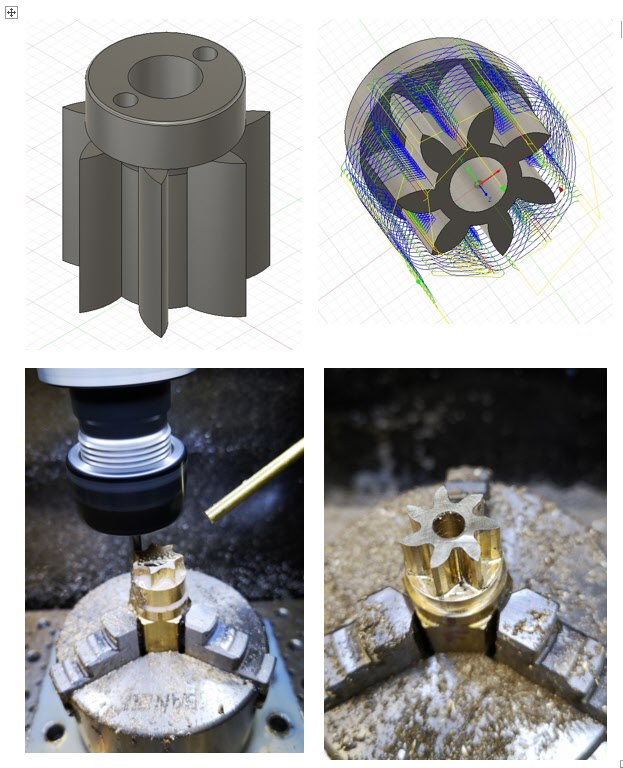
Images of the Fusion 360 process of creating the new 7 leaf pinion
The Fusion 3D model of the pinion, the CAM simulation of the leaf cutting, first adaptive cut of the leaves and rest machining final pinion

The resulting brass pinion was mounted on the arbor and the clock ran with a strong beat.   As expected the brass pinion gave less surface to surface resistance than the 3D printed part and the barrel driving weight was now able to be reduced down to 6.25kg.
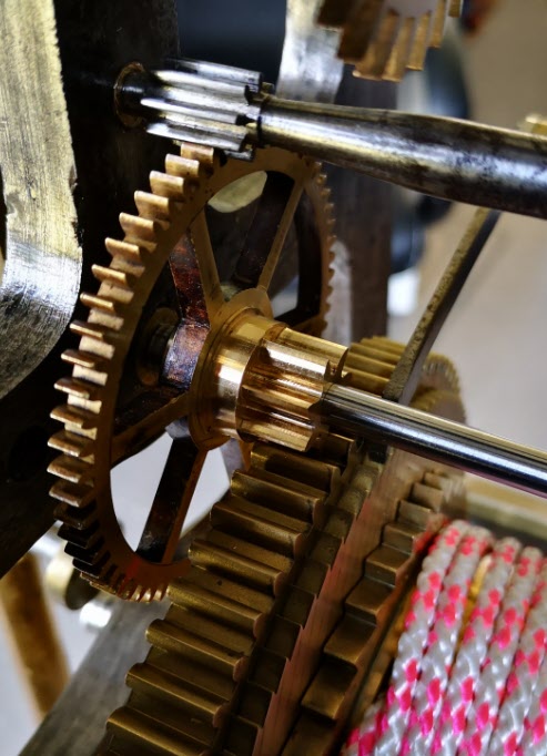
new pinion mounted in the clock
The finished pinion mounted in the clock on the new arbor

I ran my Microset Timer on the clock overnight and had a first off timing error of 5 minutes per day which was fixable with a pendulum tweak. The movement had an instability of a few seconds per day which was quite astonishing.

The conclusion of the experience is that at first glance this seemed like a conventional pinion cutting exercise …. but M1.86 cutters are not readily available.   If a cutter could have been found at less than a King’s Ransom it is likely that the resulting conventional profile would have been wrong to match the barrel wheel.   

The alternative route that was taken of Gearwheel Designer to Fusion to 3D print to Fusion CAM to CNC machining solved the problem albeit with a final weird profile.    The purists and traditionalists will groan.   There will be a gnashing of teeth and a pulling out of hair. 

Does it really matter if the result is new life for what could have become a heap of scrap metal ?

Similar or related subjects : –

Floating pressure foot for the CNCEST3040T mini milling machine

A new idea for keeping PCB material flat while milling artworks

The vacuum plate mentioned elsewhere on my blog serves me well when milling printed circuit boards on the Tormach PCNC440.   It keeps the PCB material flat and makes the cut widths repeatable when using V cutters.

The plate cannot be easily used on my CNCEST3040 due to the restricted Z height.   We have experimented with various techniques to keep the PCB material clamped flat on the smaller mill with varying degrees of success.

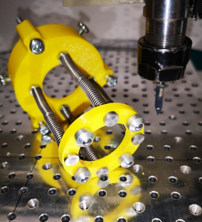
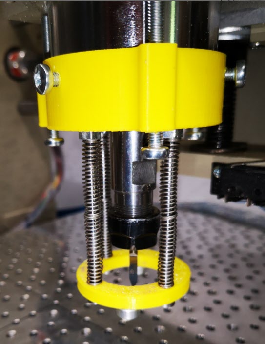
Idle hands and brain during social distancing has produced a possible solution that might be of interest and stimulation to others.   It consists of a circular pressure ring that sits around the spindle chuck and tool.   There is a second ring that sits on the spindle body connected to the lower ring with rods which have coaxial springs pushing down on the lower ring.   The magic is to use mini ball transfer units on the lower ring to press down on the PCB and glide friction free around the PCB as the cutter does its stuff.  The assembly is held in place on the spindle with 3 gripping screws.   The downward pressure is adjusted by 3 screws that press against the spindle mounting frame.

The ball transfer units come in all sizes and are very common in baggage handling systems at airports and in industrial conveyor systems.  The ones I used came from RS and have a 4.8mm ball and a M2 mounting shank

The prototype was made using 3D printed rings.   There is an image below.  Apologies for the yellow PLA but finding any PLA at a decent price is very difficult in the present circumstances.

Bottom view of pressure foot for CNCEST3040
A view of the underside of the lower ring and the four ball transfer units. In the background is the upper ring that sits around the spindle with the pressure adjusting screws and the spindle gripping screws.
Pressure foot for the CNCEST3040 in place on the spindle
View of the pressure foot in place on the spindle showing the tension adjusting screws and spindle grip screws

The idea seems to work and has produced some good consistent quality PCB prints.   It does have disadvantages in that you need to have a larger PCB blank to allow for the larger footprint of the pressure ring.   It is probably only of practical use for PCB milling but then the problem of flatness is less critical in drilling the board and routing the profile.

Similar or related subjects : –

Helping get cable down a duct

A minor post but it might help someone.

I had a need to run an armoured cable down a duct to an outbuilding.   The duct had thoughtfully been installed a long time ago with the potential for use in the future.

The future arrived and it was a daunting cable run of over 25m.   Armoured cable is pretty rigid which helps on the straight runs but when it comes to bends in the duct it had a mind of its own.

After struggling for some time I had the thought that some form of leader was needed to navigate the bends.   After searching the workshop I decided a cable tie (zip tie) might be rigid enough but flexible enough.   I snipped the fastener ratchet block from the tie and taped the residual length to the end of the cable as below.

A liberal coating of DC4 silicon grease and the cable shot down the duct and round the bends like a rat up a drainpipe.

Similar or related subjects : –

Probes and Haimer Taster Modification

I have been using a Wildhorse Innovation CNC set up probe for some time now.  It works OK but sometimes the results are not consistent.   After one frustration session I decided to upgrade it to the Hallmark ITTP probe from Threadexpress in New Zealand.  

It arrived today after nearly a month in transit due to the current lock down restrictions.  On opening the package I was impressed with the quality of the engineering.  It is a nice device.  It uses the usual 3 pronged contact mechanism.   Supplied with the probe is a tube of grease that helps protect the contact reliability.  The interface cable has a 5 pin DIN that plugs into the Tormach expansion socket and the shank is a standard TTS compatible size.

hallmark ittp cnc probe mounted on the tormach pcnc440
The Hallmark ITTP probe mounted in the Tormach ready for setup and testing.  You can also see my angel ring light illuminator and Hall Effect tool height setter.

I ran through the initial preparatory procedure and then loaded it into the Tormach 440 spindle.   Pathpilot has a number of excellent set up routines to adjust the probe and make measurements.  One of these, the Effective Tip Diameter is quite critical.  All this went to plan and very quickly.  Some initial probing gave repeatable and accurate results so first impressions are good.  

Some of the Tormach PathPilot CNC probing routines
PathPilot probe setup screen and the two probing routine screens.

I’ll give some updates as the probe gets pressed into service but my first impressions are good with repeatable accurate readings.  

In the course of checking out the ITTP probe I needed a reference cross check on the various setup measurements.   My Haimer Taster seemed a bit erratic and on inspection I discovered the axial shank holding bolt had worked lose.  This meant a re-calibration of the eccentricity of the probe point would be needed.  

The alignment process involves adjustment of four grub screws in the shank body.  These tweak the ’tilt’ of the shank to get a concentric rotation of the probe ball point.   As there are four screws I use two hex Allen keys to make the adjustments to each in line pair.  This is quicker than with a single hex key being swapped from side to side.  It is a bit like the process I use when centring a 4 jaw chuck. The adjustment is done against a dial gauge riding against the probe ball point.   Once you get the knack this process doesn’t usually take too long using the two key method.   

The frustration is that the Allen keys provided with the Haimer are a bit chocolate based and the ends chew up easily.  The result is you tighten a grub screw and the hex key end twists and gets jammed into the hex socket in the grub screw.   While trying to waggle the jammed key you mess up your carefully made adjustment.  Aaaargh !

I ground back the worn end of the Allen keys to clean up the hex profile but they quickly degraded.   In the end I took the grub screws out completely and replaced them with some M4 cap head bolts.   Joyful !

adjusting screw change on Haimer Taster concentricity adjustment
How ugly is this ? Replacement screws on my Haimer Taster

Yes I know it doesn’t look pretty but it is now a real pleasure to make the adjustments with a couple of larger T wrenches.  It is probably a criminal thing to do to such a lovely instrument but life is too short.

Next job will be to modify the arrangement of my tool sharing junction box on the Tormach expansion port so my Hall Effect tool height setter and the ITTP can share the input.

Similar or related subjects : –

Verified by ExactMetrics