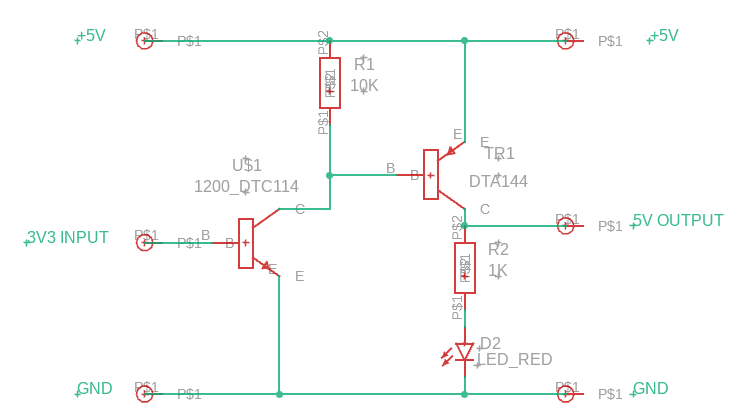
I have been deep in Arduino of late with no small amount of support from ChatGPT (that is another story). As I was working with Seeed Xiao SAMD21 devices these are all 3V3 logic operation. I had a number of instances where I needed to step up the Xiao 3V3 signals to drive external parts needing 5V logic levels. My solution uses two complementary digital transistors (these have 10k base resistors embedded), a couple of resistors and an optional LED. Here is the circuit diagram created in Fusion Electronics. Note that the DTC114 and DTA144 are available in all manner of packages so this circuit could be crammed into a very small tile for everyday drop in use.
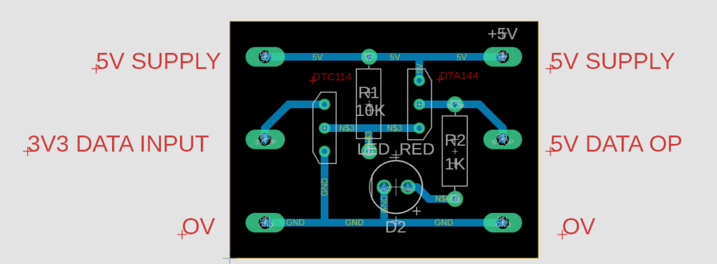
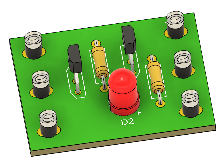
For those who like a visual of the circuit here is board layout and a 3D render.
Not rocket science but a nice simple interfacing solution.
Links to similar or related post are listed below : –
I have been working on a control system using a Seeed Xiao processor with a LoRa radio link (also with an OLED display, SD card and RTC). The system seemed to run but not reliably and was causing some head scratching. Was it my code or was it the hardware ?
After lots of playing with the code I decided it must be hardware. I had run a PCB in Fusion Electronics so all the connections were stable and reliable so what else ? …… Stupidity had persuaded me to power the LoRa modue (RFM9x) from the 3V3 stabilised output provided by the Xiao. Which might be fine when in receive mode but when the LoRa goes over to transmitter it takes a whopping surge of current. This was glitching the system.
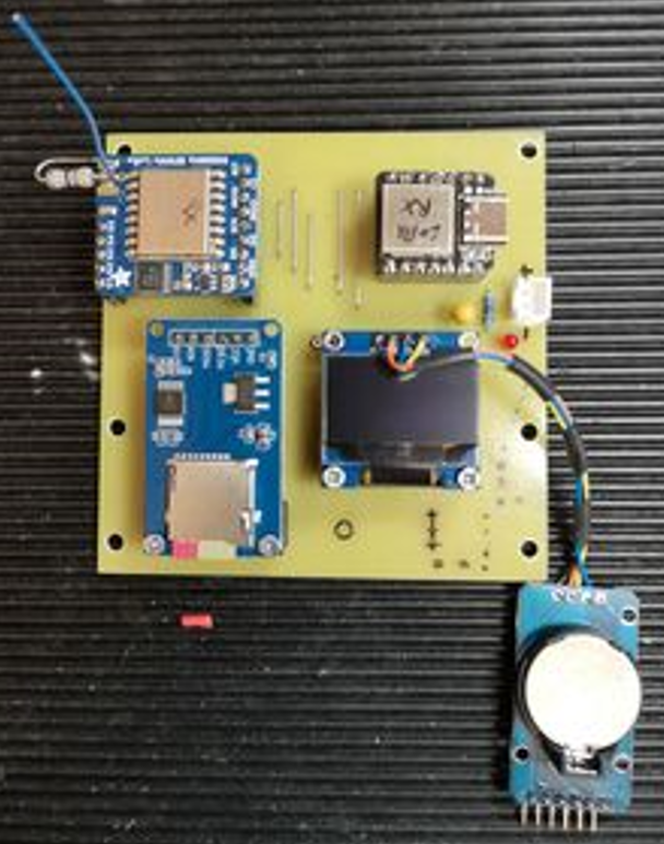
All the modules are now powered with 5V via their RAW / VCC power input pins and look after their own 3V3 stabilised rail. Problem solved, system working well. Here is a overview image of the board.
Links to similar or related post are listed below : –
After finishing a recent project I had a heap of resistors that had been used as select on test parts and now needed sorting and storing correctly. I found a design on the web for a simple Arduino based autoranging resistance meter. I prototyped the measurement circuitry for this and it worked fine. I wanted the power to the device to be from a battery source and to have this turned on via a push button switch and to auto time the ON period and return to standby.
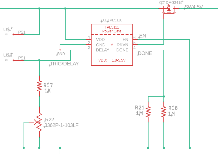
My immediate thought was to use the ICM7555 CMOS equivalent of the ubiquitus 555 as a monostable but although manufactured in CMOS technology it does have a relatively high standby current. Some web research led me to the Texas Instruments TPL5110 which can be used as a monstable triggered from a push button. The device has an incredibly low standby current of a few uA. To use the TPL5110 as a monostable is quite simple. The EN pin is tied to ground instead of to supply. The resulting section of circuitry is simple and is shown below.
The push button sits across the U$7 (supply rail) and U$8 (trigger) terminals and the ON period of the monostable operation is adjusted by the R22 trimpot. A 10 second ON period needs around 10K. Ignore the use of parallel resistors (R21 and R18) as this was to allow my PCB layout to use either a through hole part or SMD part. The switching FET for the supply is a commonly available P channel part. The particular part chosen (DMG3416) has a very low ON resistance. Note that the TPL5110 cannot be used over 5V.
The result is very legant and simple. The standby current was so low I struggled to measure it.
Note that Adafruit has a ready made module that uses the TPL5110 but this is configured with EN permantly connected to the incoming supply. In this mode the device is intended as a timing reference to turn projects ON and OFF at regular intervals in association with feedback from an associated microcontroller (via the DONE pin). If you look at the Adafruit PCB layout you will see that you will need some delicate hacking to get at the EN pin as this is linked to the incoming supply under the TPL5110.
More will follow on the completed Resistance Meter project which has an OLED display and 3D printed enclosure.
Links to similar or related post are listed below : –
A close friend has been trying to get a video feed from an Arduino so he can make astronomical observations from a gizmo he has made that will sit in the garden and observe the video in the house over USB.
We tried various methods including using the Processing app but did not have any success. The release of the Arduino Giga with Display Shield and onboard plug in camera (OV7675) has changed things. Using these integrated modules with the OpenMV application produces good quality video over the USB connection. An image of the Giga from the Arduino website is shown below.
There is a write up on using OpenMV on the Arduino forum. This is easy to follow and works very well. If I understand it correctly OpenMV loads specific firmware into the Giga rather than an Arduino based code uploaded in the normal way.
There are a few minor things to watch out for. The Giga seems to like a double reset to clear out any existing code before loading the OpenMV code. Likewise when reverting the Giga back for Arduino use you must also do a double reset.
As mentioned in the article you need to load the display.py demo example code but the demos are not available for selection until OpenMV detects the board in use. Once the boards is detected you will get details on the bottom status bar.
The other minor thing that is not immediately obvious …. if the video and the histograms are not present on the right hand side of the screen you need to drag them into view using the side arrow.
Here is a screen shot showing the code on the left hand side and the video feed and histograms on the right hand side,
The Arduino Giga is a very sophisticated module and the various example sketches that are available to run on it are impressive. It will certainly stretch my ‘cut and paste’ coding….
Links to similar or related post are listed below : –
When the Arduino Giga appeared on the market with its associated glossy Display Shield it looked like a programmers dream.
I am not a programmer. Sitting down to do a software project to me is like writing off a large lump of my remaining MTBF.
John, my close friend in France, is an also ran in this respect. We both fumble around doing cut, paste and edit development and end up with some quasi stable code that might do the job intended.
So joy of joys the Giga appeared and John got excited … which rapidly degenerated into acute frustration, hair pulling and suicide by software tendencies.
I got sucked in to help – blind leading the blind.
I tried running all the Arduino demos for the Giga Display Shield and after an inordinate length of my life had passed I concluded that any sketch with ‘#Include lvgl.h’ in it would be unlikely to run.
Slight digression. What is not made generally clear is that with lvgl library you have to edit the lv_conf_template.h file and re-save it in the Libraries folder as lv_conf.h. The edit is simply to change a 0 to a 1 and instructions are in the text at the top of the file listing. This edit enables lvgl. I spotted this and duly did as directed. Still no joy.
Out of desperation I deleted the lvgl library version 9.0.0 and replaced it with the 8.3.11 version. I then had to do the 0 to 1 and do the Save As etc routine again….
To my huge surprise this worked . See below as a simplistic overview of the changes needed.
So progress has been made and there are some nice demos to watch now that they are running OK. Note that the Arduino IDE will constantly tell you there is a later version of the lgvl library but you have to ignore this and opt for manual update. If 9.0.0 does get loaded you will have to go through the above process again to the extent of removing 9.0.0 and replacing with 8.3.11 but the edited lv_conf.h file will be unaffected so you don’t have to repeat the edit and Save As process … hopefully someone will fix it in the near future.
I would further add that not all the published demo sketches work. If you want a reliable sketch to demonstrate the camera onto the Giga screen download from Kurt’s depository on the link below.