Tormach Power Drawbar piston service

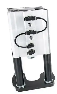
For some time my compressor has been intermittently kicking in without anything running to justify it. By chance I heard a slight hiss and then felt a small ‘breeze’ coming from the bottom of the Tormach drawbar compression cylinder stack. This device has three pistons stacked together to give enough downward pressure to open the drawbar gripping the TTS collet. The machine was installed in 2016 so the seals have done quite well to survive this long.

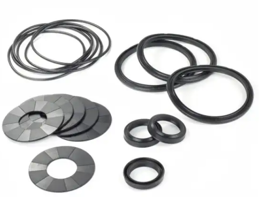
I did some web based research and found that Tormach offer a seal replacement kit so clearly this was something that was an expected service activity. I ordered the kit (which cost less than the courier charge). Here is an image of the kit.

My research also found a very old YouTube post by John Saunders at NYC CNC where he describes how to undertake the service activity. It looked like a job I could manage.

My PCNC440 model was slightly different to John’s in so far as removing the piston assembly out of the machine. On mine you have to just remove a single shoulder bolt and a pull out pin. However before doing this you need to put any of your TTS tools in the collet to relieve the pressure from the cylinder plunger head. Once this is done, turn off and bleed the air supply before removing the two air feeds. Mark them so you know which one goes to which port. Also mark the three piston sections with a Sharpie so you know which order and orientation they are in.

The piston stack has the three sections clamped together with four bolts inserted from the top of the stack. The bottom end mounting plate also has long screws that pass through spacer tubes but only fasten into the bottom piston section. Note that these spacer tubes might well have some large additional height setting washers so don’t lose them.

I suggest removing the bottom three screws first of all so you are left with just the three cylinders still held together by the top four bolts.

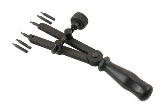
Now for a tricky part – you need to remove the large circlips that are fitted to the top and bottom ends of the piston stack. These are not easy to remove unless you have a decent tool to grip them. Basic handheld circlip pliers are unlikely to perform and you could end up search the workshop for flying circlips. For this reason you must wear some eye protection while removing the circlips. I bought in a pair of these pliers and they were superb for the job.

Once the circlips are removed you can remove the four top bolts holding the stack together and be able to split the three sections. Be careful how you do this so you see and understand what is where and the order of assembly.

The end plates that were held by the circlips are pushed outwards. All the other sections should freely slide out as appropriate.

With everything ready, start from one end of the assembly and do a logical swap out of the old seal and swap in the new one and re-assemble that section. Clean off any debris in the seal grooves and add new grease to the seals and their locating grooves. I used silicon grease.

The kit comes with 6 standard section O rings, 3 wider section rings and 3 central piston seals as shown in the image above. By swapping only one seal in and out at any one time you get a good control check that you haven’t missed anything.

My kit also had some small O rings that are not shown in the Tormach image of the kit contents. I can only assume that the kit is universal to a number of other piston types.

Update : Tormach has since confirmed that the extra small O rings are for the 770 and 1100 versions only.

The whole swap out activity took around 2 hours. This piston worked fine when re-installed back on the 440. “Phew!”

Local power USB switching circuit

Power only feed to a USB device in lieu of a computer connection

A while ago I did this write up on how I had replaced the power source on my Tormach digital height gauge so that it could run from the data cable connected to the PCNC440 mill controller computer. This removed the need of constantly having to fit new batteries.

This modification has worked very well … except when I want to use the height gauge off line when the PathPilot computer isn’t switched on. The level of frustration over the downside impact of this well intentioned modification was starting to irritate.

I had a male and female USB socket in stock along with a 4 pole 3 way rotary switch and a few AMS1117 low drop out 5V regulators. The rotary switch was one of those where you can move a selector pin to make it a 4 pole 2 way. A quick sketch and I think the problem is solved.

The logic is quite simple. Note that the colours used are just to make the diagram more easily understood and the colours chosen have no bearing on normal USB cabling colours.

In computer mode the wiring acts as a pass through connection for normal USB working. The computer is connected to the USB Male and the height gauge to the USB Female.

In ‘local’ mode the USB connections from the computer are all disconnected by the switch and power to the height gauge is provided instead by the 9V battery via the AMS1117 5V regulator and the isolating diode. Note the diode needs to be a low forward voltage device such as Schottky diode. It is not super critical as the regulator I fitted to the height gauge electronics box is a low voltage drop regulator. In total the current drawn in ‘local’ mode is around 10mA so the 9V battery will last a long time …. providing I don’t forget to switch it off (i.e. that is back to ‘computer’ mode). Which probably means I should fit a LED to the output of the AMS1117 to show the device is live on battery……

I built the device as a bird’s nest and 3D printed an enclosure. One less workshop frustration (hopefully).

One other thing to mention. The original write up detailed adding a 3V3 AMS1117 low drop out regulator to power the height gauge. See the link below.

If it is cold in the workshop the display on the height gauge can be a little dim to read. I have boosted the contrast by ‘jacking up’ the AMS1117 in the height gauge electronics box by adding a single Schottky low drop diode in the ground lead of the regulator. This increases the output voltage by the amount of the forward drop of the diode. To be clinical you should really add a tantalum capacitor across the diode to improve the stability of this modification.

Links to similar or related post are listed below : –

Tormach PCNC440 X Axis limit switch repair

A good reason why not to leave a parallel on the way cover

I was running a milling job on my 440 the other day and I had left a parallel on the Y axis front way cover when I had switched off in the evening. Next morning I switched on and homed the axis in the usual order of X axis and then the Y only to hear a crunch as it reached the homing position. The parallel had got jammed under the table front shroud. I reversed the motion, removed the parallel, homed Z and carried on.

Fast forward to the next day. Switched on and homed X which resulted in a very bad end stop stepper chatter. I stopped the motion and moved the X axis back. Something bad had happened. I stripped off my machine vice and my tooling table and removed the table front cover. The limit switch had been crushed, presumably by the parallel the previous day.

I’d like to say that this is the first time this has happened …. but it isn’t. (Hence the ding in the cover front edge …). A quick check on Amazon revealed quite a few identical looking replacement switches. There was also a twin pack available from China for much the same price but clearly much longer delivery time. A new switch was ordered and all is now up and running again (after re-tramming the tooling plate and then the mill vice etc etc …. what a pain ….)

In passing I do keep pondering the 440 limit switches and wondering if I could replace them with inductive sensors but it all looks a bit difficult having to sort out the additional wiring needed. Maybe another day ? (Sadly such a modification would still not stop me stupidly leaving things on the way cover ….)

Links to similar or related post are listed below : –

Verified by ExactMetrics