Confusion over the 10 files limit in Fusion hobby licence

I regularly see comments on forums from people who don’t want to use the free hobby licence for Fusion because of the ’10 open file restriction’. This suggests that perhaps they are used to conventional bottom-up CAD design whereas Fusion creates a powerful top-down architecture. (You can still use the bottom-up approach and this is probably why the confusion arises).

A bottom-up approach has each part of an intended assembly created in its own file and the individual parts are then brought together in an assembly file. This creates a 1+N count of files needed for an assembly where N is the number of parts involved. It also places a high demand on the creator to monitor and check linkages between the individual files.

A top-down approach starts with the assembly file and all the components are contained within that file. The file count is just 1. Clearly a top-down file could become enormous if there are lots of components but it is still one file. Unlike the bottom-up method, the linkages between the components are automatically updated.

One of the more helpful descriptions of the differences in the two techniques is the first 5 minutes of this video by Product Design Online.

The other big advantage of a top-down approach is the ability to have parametric modelling of the file. This uses a look up table of all the key parameters in a design. These parameters can be just a value or can be equation linked. They are represented in the design dimension values as text and equations. Once again Product Design Online has a good tutorial.

Although I have a paid licence to use Fusion I have never had an issue of needing anywhere near 10 projects open at anyone time but I might have had well in excess of 10 components active.

Links to similar or related post are listed below : –

DXF import to Fusion

I recently had an article printed in the BHI monthly Journal where I detailed using Gearwheel Designer to create a clock wheel and how the resulting design could be imported into Fusion using a DXF import. This would allow manipulation of the file for creating the CAM machining code.

I have a friend who uses the hobby ‘free use’ of Fusion and he was struggling to import a DXF by this method. After some exploration we decided that DXF import on Fusion was not allowed for the free hobby version. This is not clearly obvious when you look at the Autodesk site.

With this in mind we collectively investigated the differences involved using the licenced and licence free version of Fusion. This resulted in a workaround solution whereby the STL export from Gearwheel Designer can be used instead. This can create a solid model in Fusion for onward processing for 3D printing and for CAM programming.

Rather than have a long post I have detailed the process in the attached PDF write up.

Links to similar or related post are listed below : –

Adding a second monitor to your Fusion work space

Ever since I started using Fusion (over 10 years ago now … how time flies ..) I had a single wide screen Dell U2913WM 29″ monitor (2560 x 1080). This is a really nice screen to use and has lots of interface options including a Dell Display port (aka HDMI). When using Fusion it gives acres of working space. The U2913 can be picked up on EBay for a reasonable cost and this size and aspect ration makes it well worth the investment.

The frustation with single monitor working is the need to minimise Fusion if you want to dive off to do something in another app.

Lurking in the corner of my office was an old Dell monitor that only had VGA and a DVI as connector options. I wondered at the possibility of using it on my new GEEKOM mini PC which has two HDMI outputs. To my surprise I discovered that you can buy cables and also dongle adapters to allow both VGA and DVI to connect to a HDMI output (how does that work I wonder ?).

I orderd a DVI to HDMI dongle from Amazon and now have the U2913 as the main activity screen and the old Dell as the side activity screen via the DVI to HDMI dongle. This dual screen working is relatively easy to set up in the Windows display options but can be a bit confusing until you get your #1 and #2 screen selected correctly. (I intially had my mouse disappearing off the left side of the big screen and reappearing from the right hand side of the small monitor).

What a joy to have two screens. You can be deep into Fusion on the main large screen and then dive off to do a quick websearch on the other. This has had almost the same impact on my way of working as when I added my 3DConnexion SpaceMouse.

If you have a second screen gathering dust under a bench check it out for possible use. Even an old TV with HDMI interface can be pressed into service . If you don’t have a screen handy there are lots of old interface style ones on EBay at silly prices.

Go two screen ! You won’t regret it.

Links to similar or related post are listed below : –

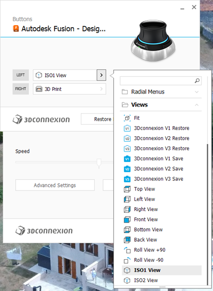
Fusion Tips using 3D Connexions SpaceMouse

You can buy the 3DConnexion SpaceMouse and CADMouse combination as a single package.   If you haven’t got a SpaceMouse you are missing a major enhancement to your pleasure while using Fusion.  It’s worth every single penny.

The SpaceMouse is a 3D manipulation mouse and the CADMouse is just a conventional mouse.   Originally when bought as a package they shared a common dongle.  I found that servicing the two devices simultaneously via one dongle led to a laggy experience.   The new versions are Bluetooth connected and are not affected in this respect. If you are considering getting one (and you should) then keep an eye on EBay.

There are two programmable buttons on the basic SpaceMouse which can be preset to shortcut functions.  I have my left hand button set to ‘ISO-1 view’ which means I can quickly reset the modelled object on screen to its home view.  You know how it is when you get totally disorientated when spinning and zooming …. Note that there are more complex versions of SpaceMouse with loads of buttons but this would be asking too much of my memory.

To set up the buttons you need to be in the Fusion Design screen.  The 3DConnexion software ‘knows’ what application you are using and which module in the application so this is important.  In a wider sense this allows the SpaceMouse to be customised specifically to every application you are using on your machine.  (Google Earth fly-by is fun with the SpaceMouse).   

To access the settings menu, click on the right hand end of the Windows taskbar and then right click on the 3DConnexions logo to open the Settings menu.   This will bring up the following menu stack. Note that you must have the Autodesk Fusion – Design… as the title.   The available button options are specfici to each of the other Fusion modules. For example I have two other functions set for when I am in the Electronics PCB design module.

If I right click the SpaceMouse button this takes me to the 3D print submenu in Fusion.   This is the same as clicking on the File menu in Fusion and clicking 3D Print.   This will bring up the following 3D print sub-menu.

(Side comment – if you haven’t discovered it yet … the ‘House/Home’ icon shown at the end of the top menu takes you to a wonderful full page view of all your recent modelling activity. Yes I know it has probably been there ages. I always was a slow developer but what joy when I found it).

Note that I have the Application box set to ‘Custom’ and the Application folder below this is pointing to the QIDI Slicer EXE file which is found in Explorer as below.  Note this is in ‘Program Files’ and not ‘Program Files (x86)’.

Click on the little folder icon in the sub-menu and navigate to and highlight the .EXE file location.  You will now have a direct boot to the slicer software you are using.  This will be activated either from the File menu or your SpaceMouse programmed button.

One extra comment – remember to set the Free Orbit setting or the Spacemouse will resist certain orientations.

Have fun !

Links to similar or related post are listed below : –

Custom Threads in Fusion

The Christmas period tends to be a lazy period to sit and wander round the web in front of the log burner instead of getting grubby in the workshop. This is greatly assisted with a glass of something and a large slice of Christmas cake accompanied by a similarly large slice of Wensleydale cheese. (It’s a Yorkshire thing. Try the combination. You might get hooked).

In the course of one of these surfing indulgencies I came across a custom thread creator for Fusion. I am indebted to Matt Beech for this creation. See his GitHub page here.

https://matthewmcneill.github.io/FusionThreadsGenerator/

He has already created XML files for BSW, BSF, ME, BSB profiles. You simply copy the XMLs into the Fusion folder on your machine. This will be found on your machine in the following path : –

C:\Users\*your user name*\Autodesk\webdeploy\Production\<version ID>\Fusion\Server\Fusion\Configuration\ThreadData

Matt’s GitHub page also mentioned ThreadKeeper which is a handy Fusion plugin that protects your custom XML files as they sometimes get deleted when Fusion updates. This little app can be installed from the Fusion App Store and will appear on the Utilities tab in Fusion.

https://apps.autodesk.com/FUSION/en/Detail/Index?id=1725038115223093226&appLang=en&os=Win64

You need to preserve your custom XML files in the ThreadKeeper folder.

Hope that helps someone. Now back to the woodburner, cake and cheese.

Links to similar or related post are listed below : –

Verified by ExactMetrics