Slope and Tilt Checker with GPS logging.
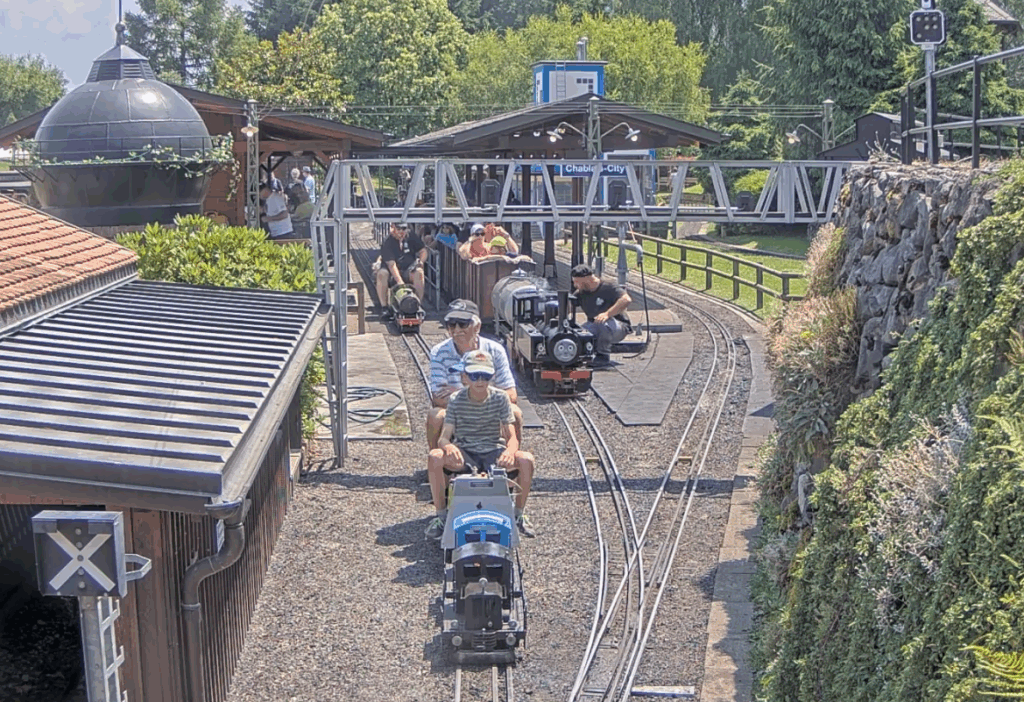
My local Model Engineering Society is very conscientious regarding the maintenance of the club running tracks. We have both ground level (7.25″) and a combined raised track for 2.5″, 3.5″ and 5″ gauge running.
The Society has decided to upgrade the support structure on the raised level track. The old wooden beams will be replaced with new plastic decking board based structures.
The upgrade is for the full length of the track (1361ft/ 415m) and will be a major over winter activity. Once the rails have been re-fitted to the new supports there will be a need to make sure the track bed is correctly aligned to match the geometry of the new support structure and the route curvature and banking.
Some while ago DroneBot posted a video about using an Inertial Measurement Unit (IMU) with an Arduino to create an electronic spirit level. This struck me as being a potentially useful device that could be enhanced for measuring track characteristics. My idea was to check the existing 5″ track profile so we had a reference before the upgrade. Once the upgrade is completed, the same measurement run could be made to help to speed up alignment.
A prototype unit was based around an Arduino Uno. The Arduino code has edits to provide additional LED ‘bar graphs’ and a sensitivity adjustment. The circuitry was accommodated on a bespoke hardwired Shield connected to the IMU. The prototype unit appeared to work very well so a more engineered version followed with a 3D printed enclosure and professional PCB both of which were designed in Fusion.
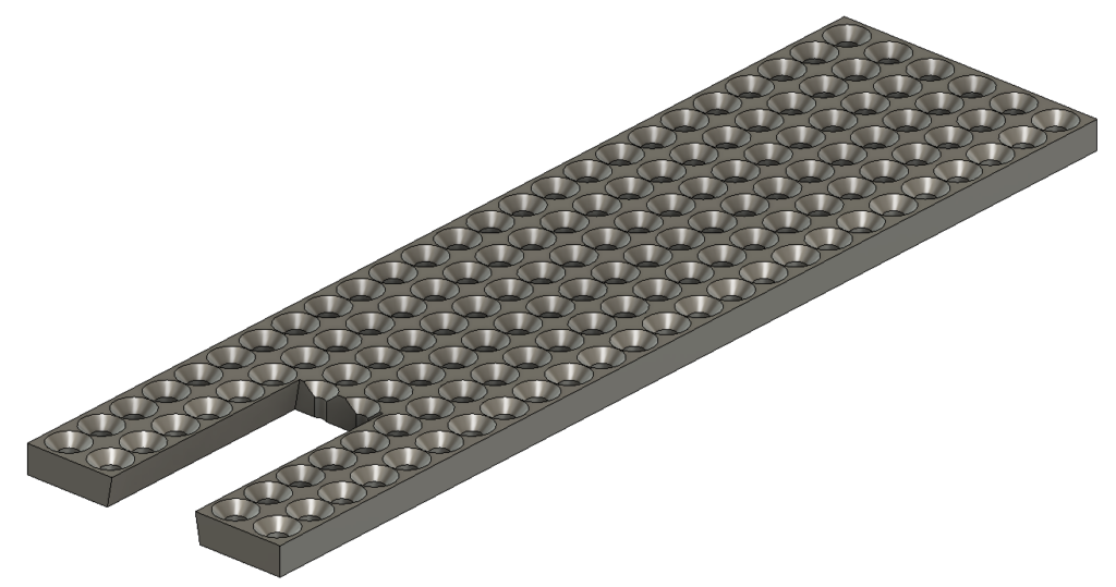
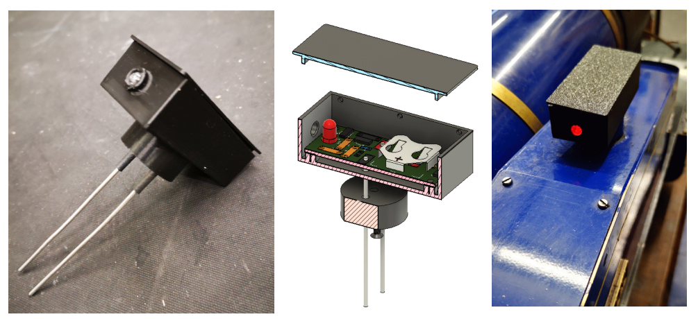
Mission creep alert …. I decided to add a GPS facility so the readings around the track could be logged. I added an OLED display and also a memory card facility to record the results for future reference. The code runs on a Seeed Xiao. The GPS unit was housed in a separate 3D printed enclosure and connected via a three wire interface cable. A 3D printed battery holder for a 12V battery completed the installation. The GPS unit takes the slope and tilt information and adds this to the displayed data. Here are Fusion graphics of the LED shield that plugs into the UNO and the GPS receiver and display.

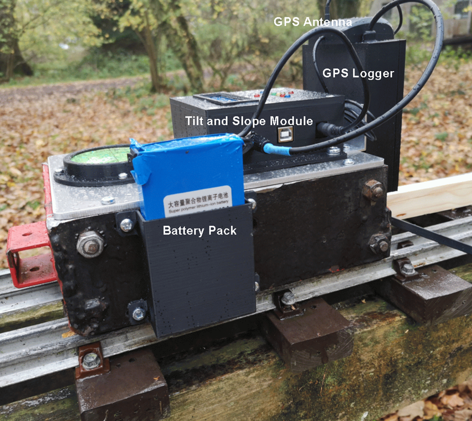
A surplus to requirements bogie was found in the club carriage shop. This had significant mass to make a stable measurement platform. The tilt meter, GPS unit and battery pack were mounted onto the bogie and for further visual cross checking a bubble level gauge was included. Here are some images (wet images …)
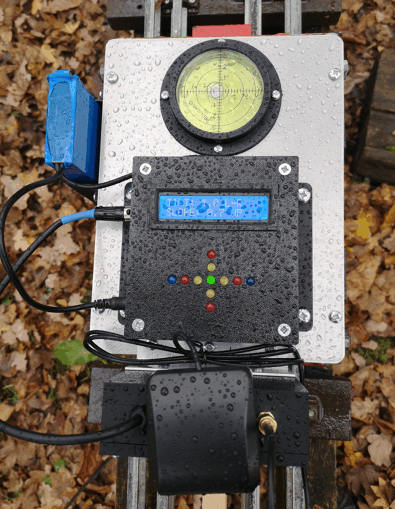
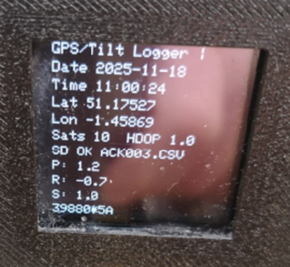
Here is the GPS unit OLED readout
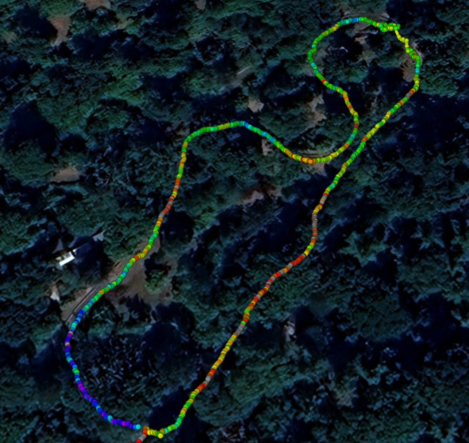
A couple of runs (actually very slow walks) were made around the track. The logged results were very impressive and highlighted one or two suspect cambers on the track. Using an App called GPS Visualizer it was possible to take the logged results and superimpose them as a snail trail on Google Earth. Visualiser also colour grades the results to provide a more obvious display of the track variations.
This has been an interesting and useful project. It might be of use to other clubs needing to check track characteristics. I have ordered a batch of PCBs for the LED display Shield and for the GPS logger from PCBWay. Let me know if these boards and the associated Arduino code are of interest.
Links to similar or related post are listed below : –
- Model Railway Track Testing Monitor
- Swiss Vapeur Parc Festival Week
- 3D Printed Jigs to the rescue
- Rosebud Fire Grate on a Silvercrest BR Class 4
- Simple Water Level Sensor for Live Steam Locos
- French Model Steam Engine Gathering
- Replacement Whistle on Polly V Steam Engine
- Bad day steaming with my 5″ Polly V live steam locomotive
- Lempor Nozzle added to Poly V 5″ steam locomotive
- Setting up the timing on a Polly V locomotive