BK3 Burgess Bandsaw motor drive shaft pulley replacement

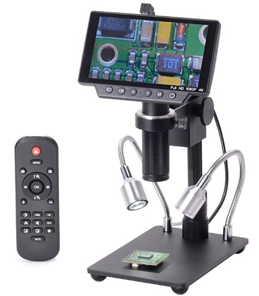
A Potential JSN Job with a Hidden Benefit

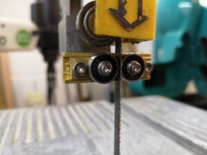
Since publishing details of the blade guide modifications on the Burgess BK3 bandsaw I have received a lot of interest and also a request for a replacement motor shaft pulley and a replacement blade drive pulley.

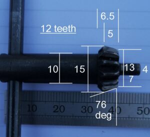
After dismantling my machine to check the dimensional details I discovered that the red plastic motor shaft drive pulley on my BK3 was severely worn to the extent of the teeth looking very distorted.  (See image below). It would appear I need a new pulley also.

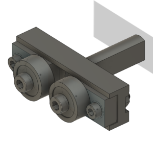
For those not familiar with the BK3 genre, the red drive wheel is a sliding fit on the motor shaft and has a helical slot in the end which locates into a cross pin through the motor shaft.   The gear wheel is forced tight into the slot by virtue of the direction of rotation during cutting.   Reading the handbook for the BK3 it seems that this pulley is designed to slide off to allow it to be swopped with an eccentric pulley mechanism when the BK3 is used as a fret saw. 

The drive belt on the BK3 is 9mm wide and 5mm pitch (with 102 teeth).  The red pulley has teeth extending axially over 25mm.   This is to allow the one pulley on the motor shaft to drive two different pulley diameters on the blade drive pulley with only a change in belt length.   This gives two blade speeds of 106m/min and 396m/min.  My BK3 never had the second pulley combination when I bought it second hand.  The BK3 is a well thought out machine and despite its vintage is very popular and commands relatively high prices on EBay etc.

Back to the plot. 

My first instinct was to 3D print a replacement red pulley and this was successfully done using the Fusion 360 gear wheel design script.  Rather than trying to model the helical slot I opted for a simpler solution of a pair of diametrically opposite ‘L’ slots.  This worked well as a concept when trialled on the 3D printed version.

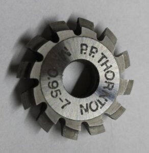
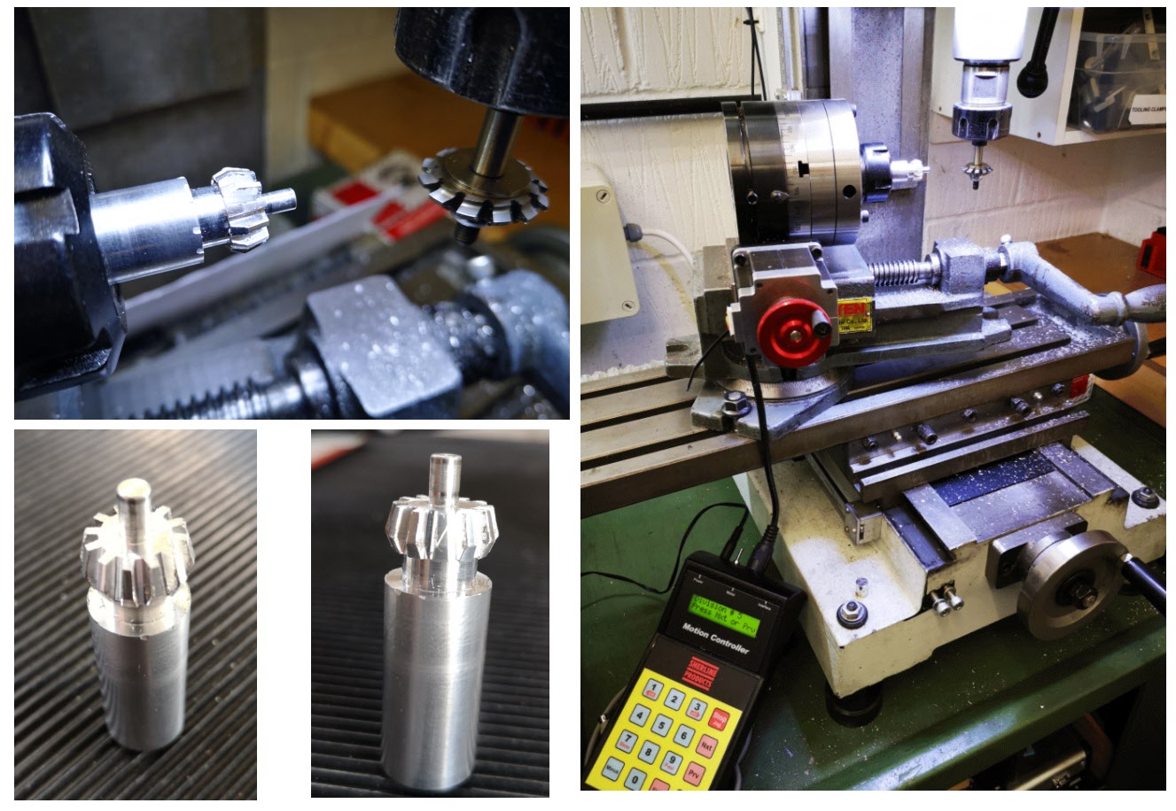
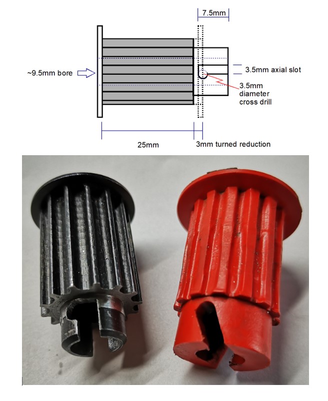
Rather than ship a PLA version to the client I opted to modify a standard off the shelf 14 tooth  x 25mm wide x 5mm pitch pulley.   These are available from Bearing Boys (14-5M-25).   The one slight problem is that the boss on the pulley needs to be drilled out to 9.5mm to match the BK3 motor shaft.   This does not leave a lot of meat on the boss.    To get the best possible strength from such a modification I opted for a steel pulley rather than aluminium.

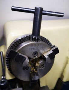
First operation is to drill out the centre bore of the pulley.   The motor shaft appears to be 3/8″ (0.375″ or 9.5mm ish).   I incrementally drilled the centre bore upwards from 5.5mm to 9.5mm but the pulley was still reluctant to slide onto the motor shaft.  Not having an adjustable reamer I ended up using a letter ‘V’ drill to get a closer fit and then a light skim with a boring bar.  After the shaft had been cleaned this combination gave a nice sliding fit 

The red plastic pulley had a tooth width of 25mm.   The teeth on the bought in steel pulley are wider (~28mm).   The red pulley only has the  single outside belt retaining collar.   On this basis I gripped the boss end of the pulley in a collet and turned back the teeth width by 3mm.  Note there is one slight problem.  The belt retaining collars are not an integral part of the steel pulley casting but a thin dished additional fitment.  The result is that at some point in the turning this fitment starts to rotate independently of the pulley body and I had to use the Dremel to cut this residual ring free before I could continue.

Having reduced the teeth width to 25mm, the ‘L’ slots need to be cut.   I cross drilled the pulley boss with a 3.5mm hole.  I then rotated the pulley in the mill jaws by a few degrees and then cut a diametric 3.5mm slot axially down to the same level as the 3.5mm hole and then hand filed the break through from the slot into the hole to create a retaining notch.   The pulley bore was then cleared of any induced burrs.

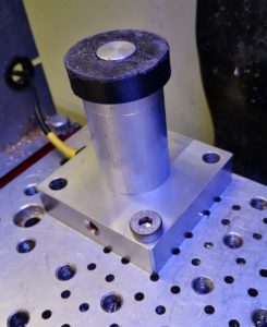
The pulley now pushes onto the shaft and with a twist anticlockwise, the shaft cross pin locates into the ‘L’ slot notch.

BK3 motor drive pulley replacement
Top image is a dimensional sketch of modifications to the standard off the shelf pulley. Lower image shows the new black pulley with a ‘L’ locking slot and the original red pulley. Note the wear on the original pulley and the helical locking slot.

So far so good.  Next job is to recreate the large drive wheel pulley.  

Similar or related subjects : –

Burgess BK3 Bandsaw Disaster and Repair

Some pieces of workshop equipment generate a sentimental attraction that is hard to break.  One such piece of kit is my Burgess BK3 bandsaw which is ancient but has up to now worked reasonably well for my needs.   I bought it on EBay from an owner in Lancashire and remember a nice day trip to collect it.

It is a very useful machine and gets pressed into use day in and day out.   That is until the other day when the blade came off with a loud twang.  On inspection the drive wheel had lost part of its blade outer retaining flange.   It appeared to be very old brittle plastic and the damage was really to be expected given the vintage of the device.

After head scratching I designed a replacement edging strip in Fusion 360 which I 3D printed and glued in place.   Fingers crossed that will give the machine a reprieve and extend its life.

In the course of looking for possible spares (no chance) I came across a reference to modifications to the BK3 in Model Engineer to improve the blade tracking and speed settings. Here is a link to the articles  burgessbandsaw2.  I am indebted to the members of my local model engineering club who came up trumps with copies of these articles for me.

The guide modification consisted of replacing the two stud guides with ball bearings.  While the machine was in pieces it seemed like a good idea to implement this modification.  The Fusion 360 3D model is shown below. The blade is sandwiched between the two ball races and these can be slid in and out and then be fixed in place with the cap head screws once the correct location is found to guide the blade.

I drew the replacement guide block assembly in Fusion 360 and milled it on the Tormach CNC from brass.   The 1/2″ bearings came from BearingBoys.

All is now re-assembled and running really smoothly.  The blade prefers to run in straight lines which is a revelation.

Update :  Since this blog entry I have made other modifications to my BK3 and these are contained in this link BK3 Modifications v2.

Similar or related subjects : –

Replacement Chuck Key for a Cowells ME Lathe

Broken Tooth and No Dentist ?

The Cowells Model Engineer miniature lathe is very popular in home workshops.   It is a well made machine and very accurate to use.

There appears to be one recurring problem with the design and that is the chuck key for the TMC3001 3 jaw chuck often ends up with broken teeth.   To understand this better you need to be aware that the Cowells chuck does not have a standard style chuck key.    It is more like a drill press chuck key as you will see from the image below.  It also has 12 teeth which is unusual compared with drill press chuck keys which usually have 11 teeth. Using too much strength trying to over tighten the chuck rotary mechanism could lead to severe machinist depression.

cowells 3 jaw chuck and chuck key
Cowells 3 jaw chuck and chuck key

I have to admit this is going to be another JSN job that slipped through the net while the sign had been left facing the wall from the last one …. a client wanted to know if I could make a replacement chuck key. 

It seems that these are not readily available as replacement parts.  So another little challenge was beginning to niggle at me. I thought about try to use Fusion  360 to create CAM for my Tormach PCNC440 CNC mill it but it didn’t feel like the right approach.  There had to be an easier way.   

While siting in the sunshine at lunch time (probably not paying attention to what my wife was telling me …. (again) …. ) I wondered if standard wheel cutting techniques could be used.   This would mean a custom made fly cutter which didn’t fill me with joy and suggested a lot of grief.  I then wondered if a standard clock wheel cutter might fit the same profile as the chuck key teeth.

With lunch over I dug out my treasure trove of PP Thornton wheel cutters and compared them with the profile of the chuck key.   The PP Thornton 0.95-7 modulus one looked a good bet as a match.   In its normal life this would be a 7 tooth pinion cutter. 

The idea looked like it might work.  I measured and sketched up the rough dimensions of the chuck key head profile which is shown below.   For ease of making a proof of concept prototype I decided to use aluminium.

First job was to profile the aluminium stock to the outline shape of the chuck key.  This completed I then mounted my Sherline CNC rotary table in the mill table vice and with some jiggery pokery managed to get the vice / table aligned at 14 degrees (90-76) to the X axis movement.   I set the centre line of the pinion cutter with the centre line of the aluminium profile.  I dialled in 12 steps on the Sherline and began cutting back and forth.   

To match the original teeth depth I had to go down to the full depth of what the pinion  cutter profile would allow.  On the prototype I didn’t bother finishing the shank of the key and below are some process images and the final prototype result.

process shots of making a cowells chuck key replacement and resulting piece
Images of the process and final result making a prototype Cowells lathe chuck key replacement.

The prototype worked.  I just have to make a fully finished steel version …… oh and remember to turn the JSN notice back over so I can’t miss seeing it next time an intriguing enquiry comes in.

Update : –  Silver steel ruined my cutter … they are really meant for brass. Looks like it will have to be a CNC method.

Similar or related subjects : –

Hall Effect Based Tool Height Setter for use with PathPilot

I had been using Hall Effect devices to modify my William Smith Gearless Gravity Arm clock and had been surprised by their ease of use and repeatable trip points.  (More about this to follow in a separate post).

I had also been frustrated with my inability to set tool heights reliably in PathPilot despite using various methods all of which didn’t want to agree with each other.

This resulted in the construction of a Hall Effect based Tool Height Setter that appears to solve the problem.   The write up is lengthy so I have committed it to PDF for download but here are a couple of images to give you an idea of the result.

sketch view of tool height setter concept
A simple cross section sketch of the tool height setter concept using a Hall Effect sensor

 image of finished tool height setter using a Hall Effect sensor

Finished tool height sensor mounted on the PCNC440 milling table

Link to Tool Height Setter write up

Similar or related subjects : –

New Microscope

Technology Upgrade

Quite some time ago I mentioned a really low cost simple microscope that I think John Saunders had recommended from Amazon.   The device has served me well even though it was quite basic.

I recently had a job to do where I needed to see and measure a very small part I was making.   The simple microscope was struggling to cope or at least I was struggling to cope with it. Looking on the net to see what the current technology could offer I spotted a device on Amazon that looked interesting.

KKMoon Microscope from Amazon


https://www.amazon.co.uk/gp/product/B07VL44TJT/ref=ppx_yo_dt_b_asin_title_o01_s00?ie=UTF8&psc=1

It was a bit more expensive but nowhere near a ‘proper’ professional optical product. Having taken delivery it is very impressive. 

It can act as a simple standalone viewer using the built in screen or can be externally connected via HDMI to a monitor or (and this is the impressive bit) it can be connected to a PC via a superb application that has so many bells and whistles it will take me ages to understand all the functions.  The sensor is a 16 Megapixel Sony CMOS 1/2.3″ HD device and video output can be 4K/2k/1080P.  Magnification is up to x300.

So I am well pleased with the investment and  it will certainly earn its keep.

Similar or related subjects : –

Verified by ExactMetrics