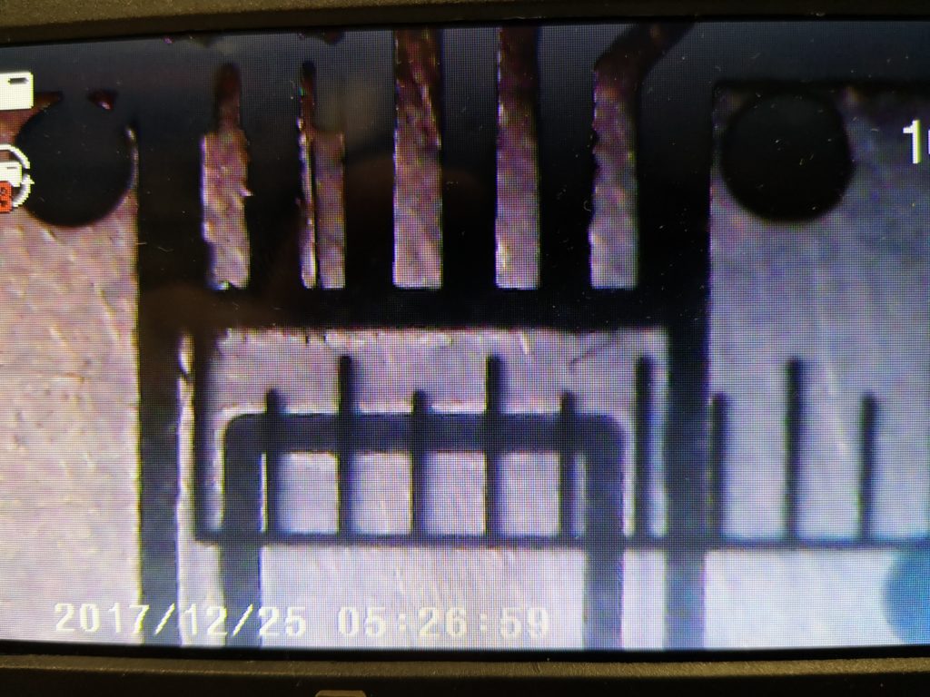
Previously on Woody’s Workshop … I had spent time trying to get a consistently level PCB blank clamped to the tooling table ready to mill the traces using CNC. The results were not too bad but being anally fussy it left a bit to be desired, particularly if the board had a large area which magnified the variations.
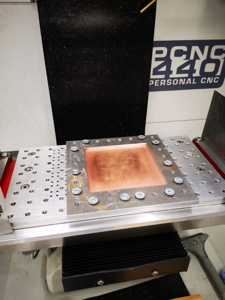
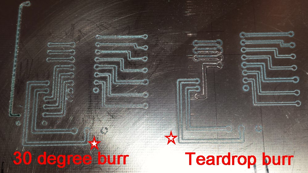
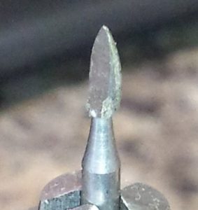
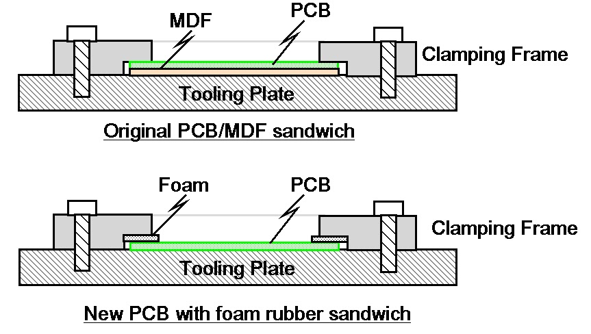
Any variation of the level of the PCB top surface will produce variable width cuts when using a V shaped cutter. I had machined a clamping plate which was a simple open frame with a clamping step equal to the PCB thickness (1.6mm) and a sheet of MDF or hardboard as a sacrificial backing board.
Despite having more clamping screw holes than a magazine burst from an AK47 I still ended with the corners of the PCB being a few thou lower. Results were shall we say ‘variable’. I had reason to run a new prototype board this week and once again hit the same frustration. In the end it was a sit and look at it and have a think session.
The resulting revelation was maybe the sharp edges on the step are applying too much pressure ? What if I were to be more gentle with the clamping ?
I cut some strips of thin foam rubber and put this into the step such as to push down on the PCB. As a quick test I only fastened the frame down using the four corner holes.
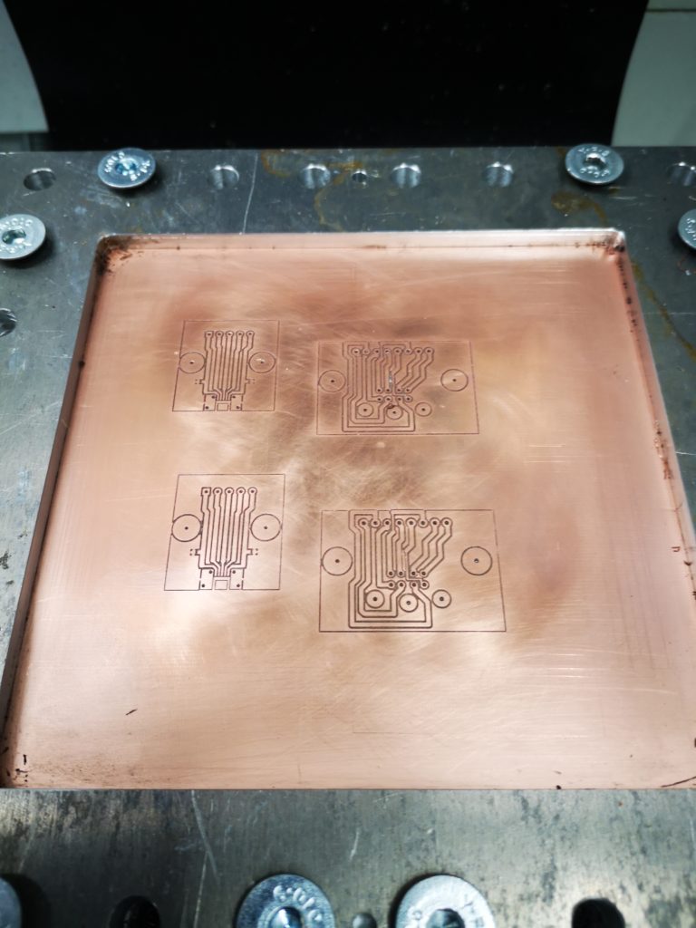
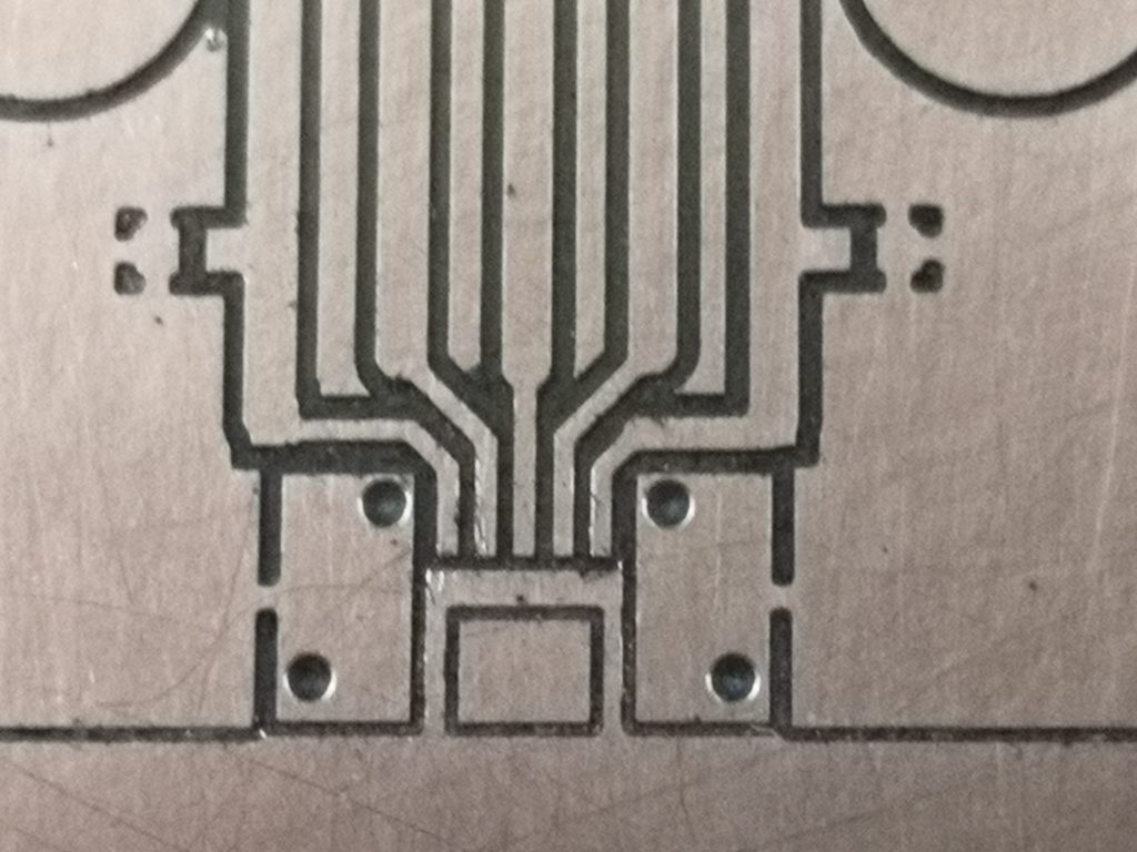
Absolute magic. The PCB surface hardly moved the Hamer needle at any point on the surface. Milling result was an artwork to be proud of.
Issues – the current step on the clamping frame is meant to clamp to a hard stop based on the sum of the PCB thickness and the sacrificial material thickness. Adding the foam meant I had to do away with the sacrificial board. The frame step therefore needs to be deeper. The sacrificial material is essential to allow drilling to take place without breaking the drill as it runs into and potentially damages the tooling table. (For the board in question I drilled to only 1mm and then over drilled by hand off line to the mill).
So a worthwhile bit of experimenting and hopefully a better result going forward
Similar or related subjects : –
- Further experiments milling PCBs
- Editing irregular PCB shapes in FlatCam
- Vacuum table update for PCB milling
- Update on CNC milling printed circuit boards on a homemade vacuum table
- Experiences and understanding FlatCAM PCB milling program
- Clamping of printed circuit boards while milling tracks follow up
- A Mini Vacuum Clamping Table for PCB Engraving
- Stretching FlatCam and PCB milling on Tormach PCNC440
- Milling Circuit Boards Update
- FlatCAM Update and experimental copper cutting
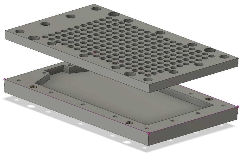
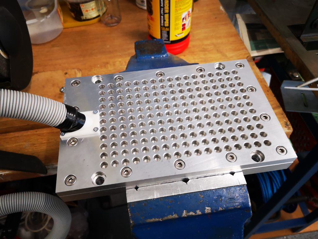
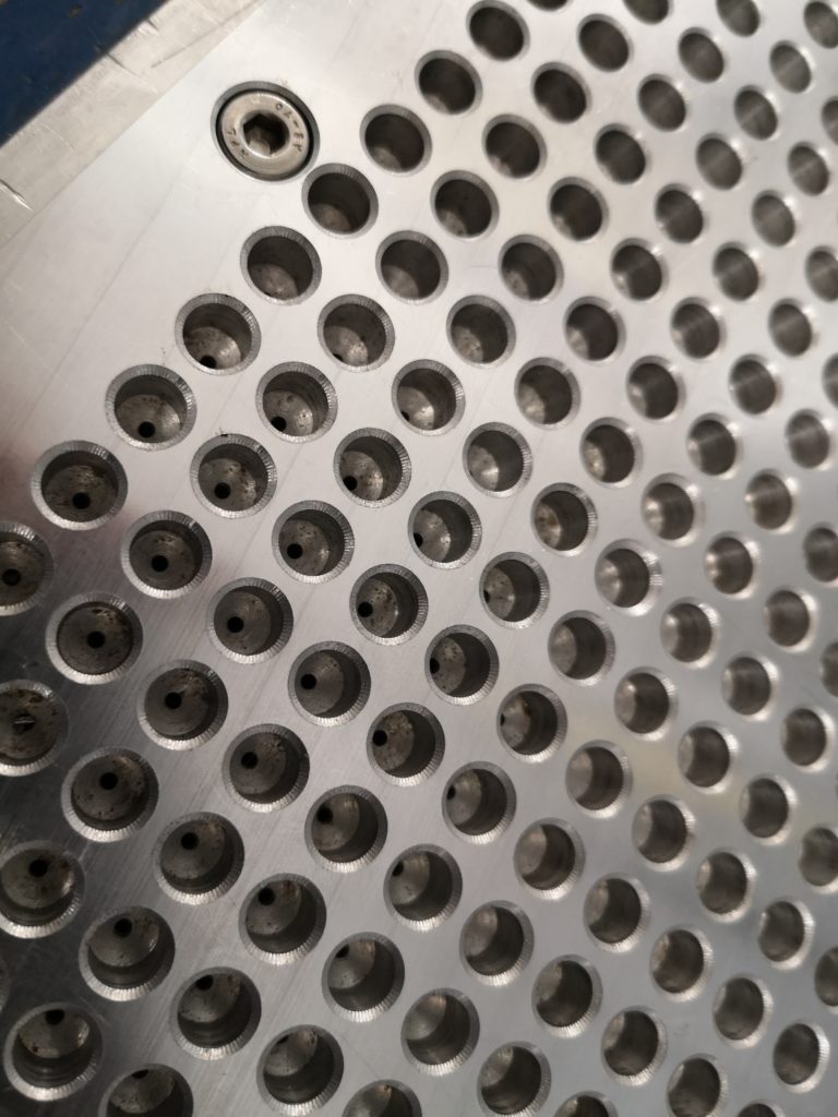
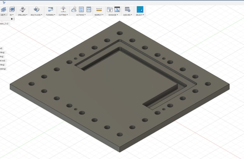 The outer holes are for the M8 clamping to the table and the four smaller holes are the tooling holes. Being tight with my materials I did not want to just mill out the centre of the plate and have a mountain of swarf (chips). Instead I designed it with two slots as shown, one for the clamping surface and one that almost cut through the stock. The partial cut was to ensure the central piece did not flip out once cut free and damage my cutter. First one half was drilled and cut and then the plate was rotated 180 degrees and the second half cut. This left the central island just held in place by less than 0.5mm of material. This was easy to hand cut through to liberate the central area. The plate was then turned over and the cut edge cleaned using the same tooling position and doing the same 180 degree rotation. To my surprise the rotation process on the tooling pins worked very well with only a minor step transition at the overlap point on all cuts. This was probably more down to my 3.7mm tooling pins being not quite concentrically turned from 4mm silver steel. With this finished I now had a much more robust clamp for the PCB material. I had made the clamping step 4mm deep so I could put sacrificial backing boards behind the PCB being run. This would allow drilling through as needed. Checking the flatness of a clamped PCB blank with my Haimer showed variation of a few thou in the top surface of the PCB Z position. The worst case variation in Z was at dead centre where the PCB’s natural bow was most dominant.