Black & Decker Cordless Dustbuster 18V
In the workshop I have a large ‘conventional’ vacuum cleaner with a long hose and cable. It gets used for not just cleaning away the workshop mess but also as the vacuum source for my homemade vacuum table.
When you have a ‘small mess’ that you can’t be bothered to drag out the large vacuum, undo the hose and cable for what will be a two minute session, it is nice to have a quick alternative. I have settled on the Black & Decker PD1820L cordless 18V.
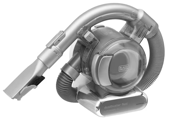
It has a short flexible hose which does not have to be deployed as it clicks into the body of the device. It has a couple of attachments, a brush style and a narrow ‘get into tight spots’ option. The charging plate is simple to seat the device into. All in all it is a handy convenient device that probably gets more use than its big brother.
The dust chamber has a grilled plastic pre-filter with a secondary hepa style replaceable filter insert. The general complaint is that the hepa filters need constant replacement as they do clog quickly. I have just two of these filters.
When one gets clogged I knock out the majority of the dust particles over the rubbish bin before soaking it a container (a large yoghurt pot) which has a couple of teaspoons of dishwasher powder that has been diluted in hot water. Leave to soak for a day or so and then rinse and dry on a radiator or similar. Using this method you only need to buy the one spare filter and just keep cycling the pair round.
I use a similar method for cleaning the spa filters in France. The only thing different there is that I use a ‘green’ Eco Ver dishwasher tablets. If you use a normal tablets there tends to be a residue in the filters that leads to foaming in the spa.
Links to similar or related post are listed below : –
- Small handheld vacuum cleaner
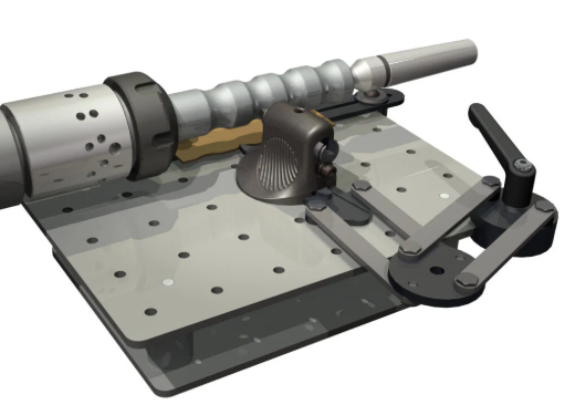
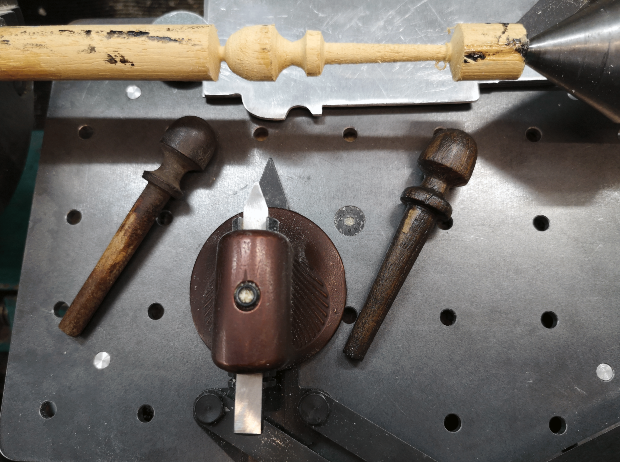
- Eccentric Engineering Turnado freehand turning tool
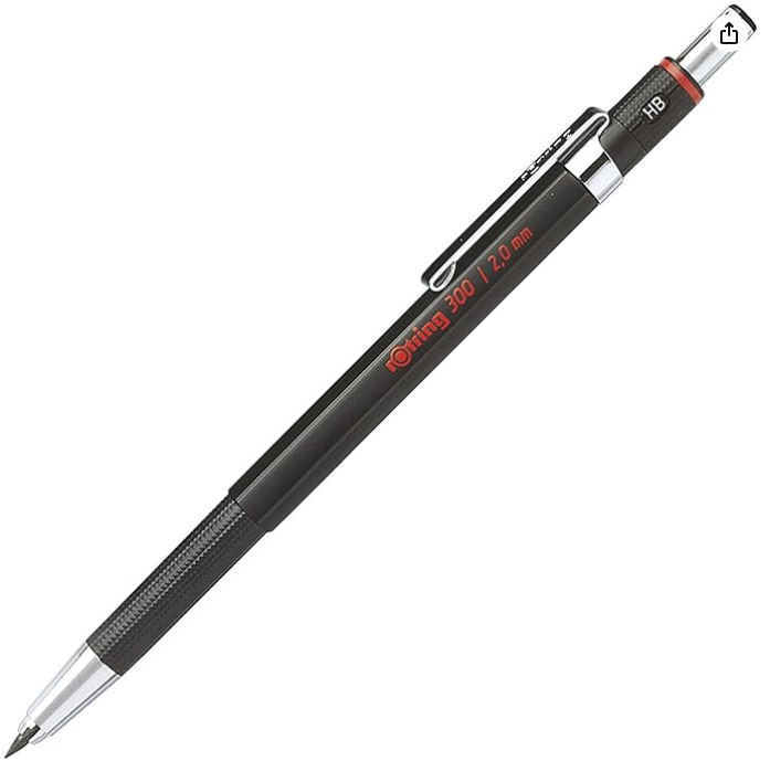
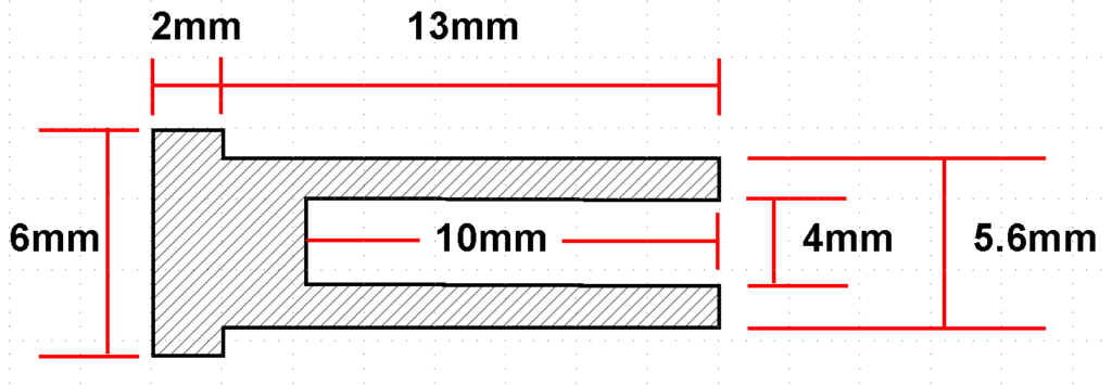
- Rotring 300 2mm clutch pencil modification
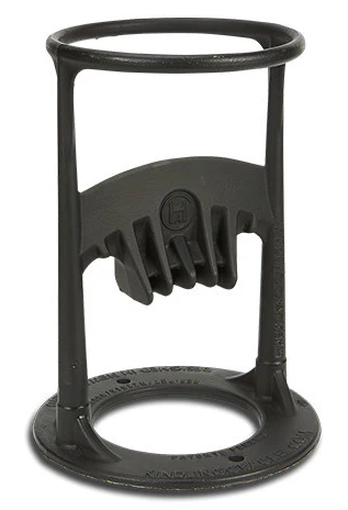
- Kindling Cracker – a safer option
- SINO SDS2MS DRO repair
- A useful Amazon sourced small item storage system
- 3D Printed Threads Modelled in Fusion 360
- Three axis stepper controller PCB in stock
- Myford Super 7 Large Bore depth stop
- Tangential Lathe Toolholder for Myford Super 7