BK3 Bandsaw Lazy Susan Turntable Update

Adding a Rotation Stop Pin

There is no doubt that adding the Lazy Susan rotating base to my BK3 Burgess Bandsaw has been a good move. Being able to adjust the orientation of the BK3 to suit the material being cut makes life so much easier.

The one issue that has come to light is when adding heavy pressure to the cut I was having to push the material with one hand while trying to stop the BK3 rotating with the other hand/arm/knee.

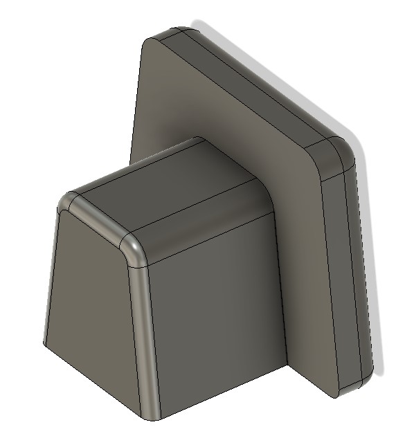
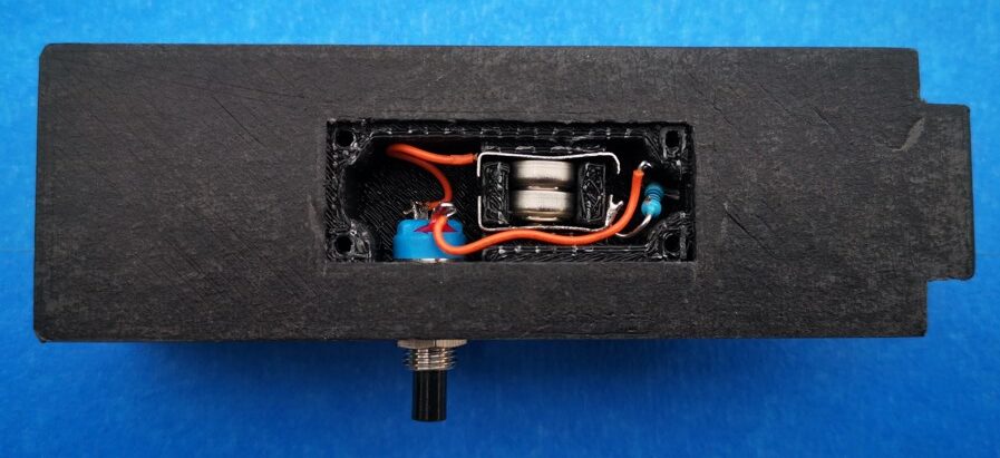
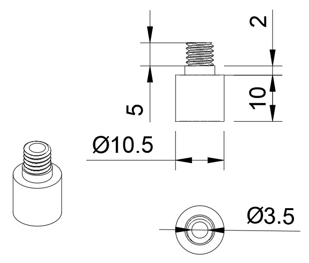
Following one such episode I have added a stop pin that locates into preset holes in the new wooden base. I used one of the four unused holes in the original BK3 baseplate as the pin locating point. These holes are 6.5mm diameter (probably 1/4″ originally). I could have used a 6.5mm rod pushed through one of these holes into the new wooden baseplate but the BK3 baseplate metal is only 2mm thick. This would probably have resulted in a sloppy hold. Instead I made a small boss and fastened this into the BK3 baseplate left rear hole. The boss clamps on the underside of the baseplate and is held in place with a M6 nut and washer. The 3.5mm through hole provides a rigid guide for the locking pin. The sketch for the boss is below.

The four original holes in my baseplate were a bit rough and the one I chose to use needed a deburr so the shoulder on the boss sat flush to the bottom side of the BK3 baseplate.

The new wooden baseplate needs to be removed from the Lazy Susan so the boss can be mounted in place. Once the boss is in place the Lazy Susan is refitted. A 3.5mm rod is lightly hammered into the wooden baseplate to mark the desired lock positions. The Lazy Susan is then removed again and the wooden base drilled through at the marked locking positions.

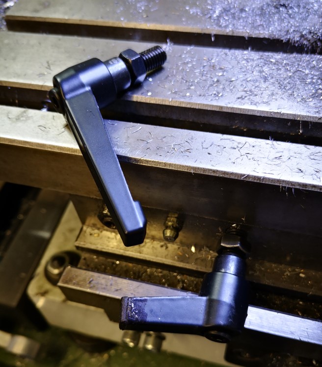
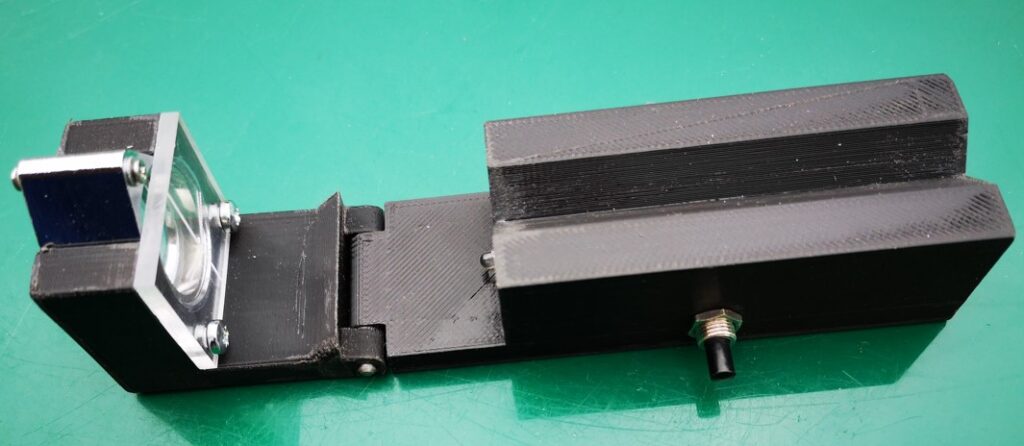
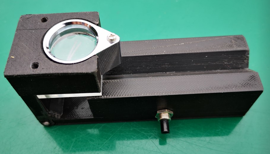
The locking pin is a length of 3.5mm silver steel (drill rod) bent at right angles with its ends nicely rounded. The rod is ~45mm on the locating length and ~25mm for the grabbing handle. Here is an image of the finished construction.

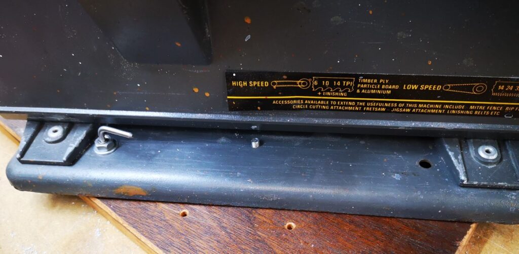
This simple modification works extremely well and with hindsight should have been in my thinking when I first fitted the Lazy Susan.

A full list of my BK3 modifications are here

Links to similar or related post are listed below : –

Noga Tool Christmas Present

Every workshop should have one

There was a recent thread on the MEW forum about Noga tools. It led me to download the Noga catalogue as a PDF. I am amazed at the technology that Noga produce to just remove burrs.

They are lovely tools and well worth the investment. I particularly like the external Rotodrive EX18 countersink. This is very handy for cleaning up the end of a newly threaded rod so the new thread will ‘take’. So quick and easy.

What really took my fancy in the catalogue on page 51 was this combination tool. That’s certainly one for my Christmas list.

No affiliation to Noga. I just like their technology.

“Better to have it and not need need it than to need it and not have it” – Jimmy Diresta.

Links to similar or related post are listed below : –

Edge Technology Lathe Tool Setter

A useful tool for setting lathe tools on centre

There are many ways to set a tool centre line on a lathe. The most basic is just to trap a 6″ rule between the workpiece and the tool edge and adjust so the rule is vertical.

One gizmo I picked up at a trade show from the Machine DRO booth is this very useful tool by Edge Technology.

Edge Technology Lathe Tool Alignment jig

It is simple but clever. You mount the rod in the lathe chuck and then rest the bubble anvil on the tool edge. Edge Technology also do a more refined version with a calibrated scale.

It is not something that you use every day but every now and then I have a session with it and go through all my QCTP tooling and tweak them.

(If it has been one of those ‘not settling to anything’ days you can at least switch the workshop lights off with a warm glow that you did something useful …)

In the UK they are marketed by Machine DRO

(I have no affiliation to Machine DRO or any other manufacturer or supplier I might mention in my write ups but I will mention any nice pieces of kit I come across or use).

Links to similar or related post are listed below : –

Truncated Lock Levers

Restricted space modified lock levers

Each of the axis locks on my VMB mill uses two M8 cap head screws in association with a lock nut. This works OK if the hex driver is in reach …. but it never seemed to be …. so I decided to remove the cap head screws and fit lock levers instead. Lock levers come in male and female format and various thread sizes. The M8 versions all have 40 to 50mm long lever arms. This length doesn’t work comfortably in the space constraints on the VMB X and Y axis but is fine for the Z axis. Similarly I also had to reduce the length of the lever thread.

The obvious solution was to cut down the length of the lever arms. The trouble with this was the raw open end of the arm looked naff and did not sit easily with my usual perfectionist approach. The solution via Fusion 360 was to create some 3D printed end caps which I then bonded in place with Araldite. This finished the job properly.

Fusion 360 modelled end cap for the shortened lock lever arm open end

The Fusion 360 3D modelled end cap printed in under 4 minutes with a further 5 minutes for the Araldite to cure. I now have a much more elegant looking solution.

Full length lock lever and the truncated version with 3D printed end cap mounted on my VMB mill

All of which has led to a rethink the lock levers on my Quorn tool grinder. I get in a real mess with these clashing with each other. Where did I put the Araldite ? …..

Links to similar or related post are listed below : –

Gadget Builder Drill Point Inspector

A 3D Printed Version of John Moran’s Drill Point Inspector

John Moran has an excellent website that details all manner of engineering projects. He is a keen advocate of four facet sharpening of drill bits and he details a Drill Point Inspector device for checking grinding results. I quite liked the concept and thought it would also be a useful asset for checking the condition of milling tools. The design uses a small inspection eyeglass magnifier lens that can be flipped from end view to side on view for tool tip inspection.

Those who know me through my blog will know that I am of a lazy disposition which tends to cause me to step back and look for an easy way to manufacture something. John’s design immediately suggested to me that a conversion to a 3D printed equivalent would be a practical solution. I also picked up on a comment that John made that you needed good light to be able to view the drill point clearly. As a result of this comment, the 3D design evolved with the addition of a simple LED illuminator. I also added a ‘right angle stop’ so that when hinged for side viewing, the lens was held more repeatably.

Because the inspector will only be used now and then, I opted for two small hearing aid batteries as the LED power supply together with a single resistor and switch. I printed two slots in the cavity for a pair of nickel silver battery contacts to sit in.

View into the battery and switch cavity. The battery contacts are bent pieces of nickel silver or tinplate

The design was modelled using Fusion 360. The two parts of the body were 3D printed. The Perspex viewing graticule was CNC milled to size and the reference comparison lines were also engraved on the CNC. The inspection lens is available from many sources on EBay (x30 21mm). The inspection screen mounting holes are 3D modelled. Here are a couple of shots of the finished model.

3D Model of John Moran's Drill Point Inspector showing the model flat for end viewing of the tool
Model hinged flat for end viewing of the tool (the LED is just visible)
3D Model of John Moran's Drill Point Inspector showing the model hinged at right angles for side viewing of the tool
Model hinged up for side viewing of the tool

Note that the addition of the LED illuminator needs the modelling of a cavity on the bottom surface of the main body. When printing this part it will be necessary to have the printer provide support structures. I also printed a cover for the cavity but this could be an offcut from an old credit card or similar thin plastic sheet.

Once printed I found the parts needed slight ‘fettling’ to remove any surface striations on the V block section, in and around the hinge section and around the eyeglass mounting slot. That aside it printed fine and the parts went together easily. More to the point it works well and is a useful tool to have to hand.

The Fusion 360 file and STEP files for the main two model parts are available in the following ZIP file. If you need additional information please get in touch.

Links to similar or related post are listed below : –

Verified by ExactMetrics