Why didn’t I think of this before ?
I have attempted various standalone soldering iron mounts for inserting brass threaded inserts into 3D prints. None of these ended up being something that I would rush to use with all their various shortcomings.
My brief for a design was that it had to clamp hold my Lytool solder iron (this takes the Hako 900 series bits), ensures the the action on the insert was perpendicular to the workpiece, had a return spring and a depth stop. Most of the designs I had seen were standalone devices.
My outline brief matches a standard drill press action – perpendicular action, return spring and depth stop. Why not use these attributes ?
The result end up being quite simple. A soldering iron mounted on an arm that has an arbor for mounting in the drill press chuck. Here is a garishly coloured Fusion graphic image.
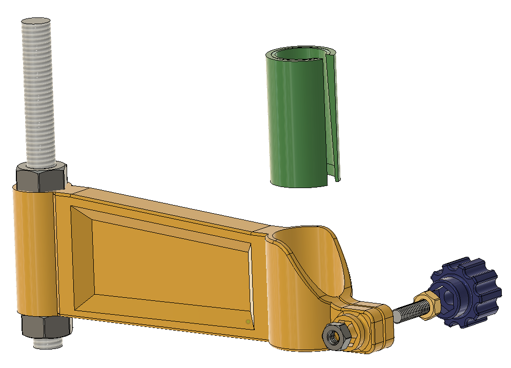
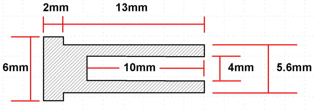
The arbor is a length of M8 studding held firmly in the mounting arm with a top and bottom nut. The soldering iron clamp holds an adapter sleeve to match the soldering iron profile. The clamp is tightened with a 3D printed knob which has a retained M4 nut and thread and this mates with a retained nut in the 3D printed arm.
Here is the real thing.
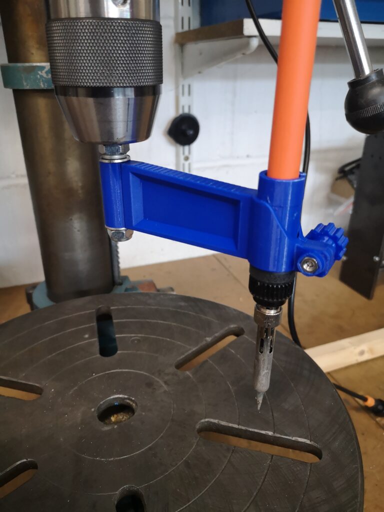
It clearly doesn’t have much appeal if your 3D printing is in the back bedroom and your drill press is out in the cold damp garage….
If you want the STEP files let me know.
Links to similar or related post are listed below : –
- Hybrid 3D brass threaded insert tool
- Tap shank adapter for 4mm AF hex drivers
- Qidi Slicer auto support error on my part
- Qidi X Smart 3 revised fan installation
- Qidi X Smart 3 tweaks
- Qidi X Smart 3 special weekend pricing
- Stop losing Qidi ifast 3D prints down the chamber front gap
- Fitting a Bento air filter to a Qidi ifast 3D printer
- 3D Printed Brass Threaded Insert Soldering Iron Stand
- eSUN filament reel silica drying pod