November update

Mainly jobs in France and 3D printer choice plus thin wall printing

Sorry it has been quiet on my blog. We took a few weeks off in France. This should have been relaxing but things got in the way. Our elderly French neighbours seem to store up their ‘can you just have a look at’ jobs for when we arrive. This ranged from leaking coffee percolator, dead washing machine, DVD player not working etc. I don’t mind this because in return they keep on eye on the house for us. The only frustration is that I am not as well kitted out with repairing resources as I am here in the UK.

From our point of view the spa was coming up with two error messages – no flow and UV lamp needing changing. The flow problem was traced to the flow sensor. This I think might be a Hall Effect sensor that is tripped by a magnet on a thin metal strip that is bent towards the HED with the water flow. It could equally and more likely be as simple as a reed relay that is tripped by the magnet. I managed to source a replacement from a French source.

The UV lamp was not so straightforward to replace but I did question the validity of the message on the display. The UV bulb has a recommended life of 2 years. The software in the spa has a clock which we reset to current time and date when we turn the spar on for each visit. The UV bulb life is based on the clock count down. I am not sure whether it is recording the period from clock time to clock time or the actual running hours given our intermittent short period visits. I carefully checked that the bulb was still glowing brightly and then reset the countdown timer. I’ll take out a new bulb next visit.

There were various other distractions but the weather was amazing for October with one or two days reaching 30 degrees.

Arriving home I have landed a project that requires 3D printing items that need a Z height of over 200mm. The project also needs thin wall printing. My trusty but now dated Sindoh DP200 falls short on this. The Sindoh has been a loyal and reliable device giving me few problems and repeatable quality print results. The main frustration has been having to be single sourced on Sindoh PLA or ABS as their filament has to have the associated custom Sindoh personality chip. Later versions of the Sindoh range (1X and 2X) purport to allow third party filaments to be used.

This has led to some soul searching. I am now comfortable with the concepts involved with 3D printing and have felt for some time that an upgrade of printer was on the cards. My wish list clearly needed to include allowing 3rd party filaments and not just PLA and ABS. (Carbon fibre being very attractive). The list also included an increased build volume and possibly a dual nozzle.

Clough42 has had some recent videos focussed on the Qidi products, namely the I Fast and the X-CF. Qidi also have the X Max. All three of these printers have Z heights of 300mm. Pricing is not low but these are all enclosed printers. There are many other Qidi review videos on YouTube. Qidi seem to be hot on support which is good news. So I have a debate raging on whether to jump and which way. Here is my basic spreadsheet comparison chart which includes the Sindoh 2X as a possible contender. Sindoh might be moving away from their own models and working with more higher end products under their brand Fabweaver. There are some interesting technology articles on the Fabweaver blog.

I investigated the thin wall printing issue and came across a very interesting post by Wayne from SoarKraft. Wayne uses thin wall printing on his slope soaring glider models and he details how Cura and Prusa slicers (free downloads) have only relatively recently caught up on this whereas Simplify 3D (subscription) has had it as a facility for sometime. Wayne’s video is worth a watch. The Qidi printers like many other manufacturers use a variant of Cura. There is a very good support article on the Simplify 3D site that relates to thin wall printing.

My printer upgrade debate continues but the I Fast looks the most attractive. The only problem is it has a large physical envelope and I don’t have a plan where am I going to put it in the office/workshop……

Links to similar or related post are listed below : –

3D Printed Four Facet Sharpener

A Hybrid Version of John Moran’s Elegant Design

While investigating four facet drill sharpening, I came across John Moran’s website which detailed his design for a four facet drill sharpener.   Four facet sharpening is popular for providing more accurate starting of a hole, less drilling pressure, more accurate hole size and better retention of drill point sharpness. John’s design is intended for sharpening 2mm to 12mm drill bits.

I have a Quorn grinder but it is not something that I can quickly pull out from under the bench to sharpen the odd drill.   John’s design looked easy to set up and use and certainly easier to carry. I have been working with him to produce this hybrid version. I recommend that you read John’s write up before embarking on either his original design or my 3D printed hybrid version. He also presents a YouTube video on how to use the sharpener.

https://gadgetbuilder.com/DrillSharp.html#Facet4

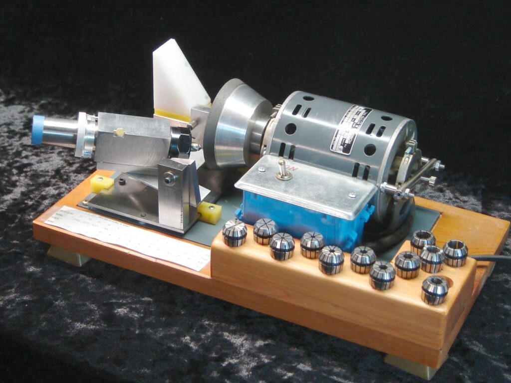
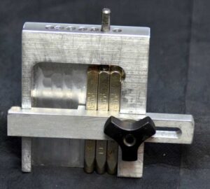
Here is a picture of John’s finished design. Very nicely finished and presented.

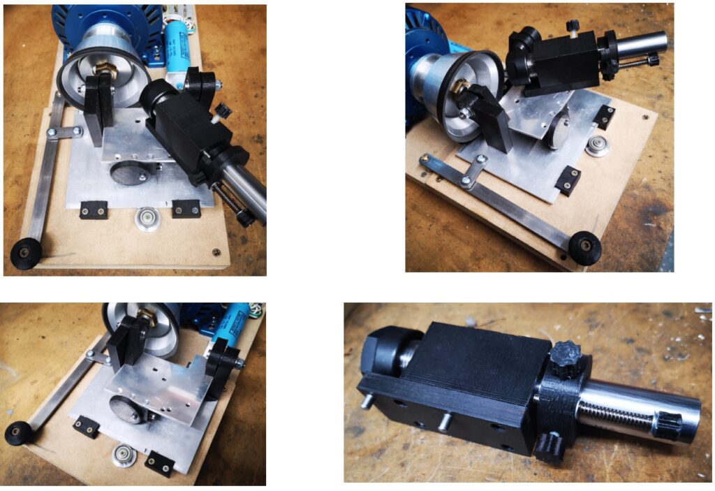
Here is a picture (not quite so pretty …) of my 3D printed hybrid version. A new baseplate might be in order to smarten it up.

The concept of combining 3D printed components with essential metal parts works very well and the resulting sharpener appears to be stable and repeatable in its results. There is a huge advantage in combining technologies in this manner. All the ‘boring’ or ‘dreading to make / leave until tomorrow’ parts are easily produced on a 3D printer and the remaining metal parts are straightforward to produce with conventional resources and skills.

Rather than go into details as a blog post, below is a link to a ZIP file that contains my full write up, 2D PDF drawings of the metal parts, STEP files of the 3D printed files and the raw Fusion files for those wanting to tweak.

If you can’t work with STEP files then let me know and I will run STL versions. STEP files are more accurate than STLs and also have the advantage of being more easily editable than STLs.

I think you will be impressed with the end result of John’s design.

If this write up or my general waffle is of interest then please subscribe to receive notices of new posts. If you build the sharpener and it works let me know. If it doesn’t work and it’s my fault for not providing enough information than email me so I can correct things.

As an alternative to a 3D printed version you can watch Mark Presling on YouTube who has recently construct the same sharpener in metal.

UPDATE

I have already had some feedback on the 3D printed design so some of you are quick off the mark.

This feedback related to the friction of the collet holder shank in the block and also the print roughness against the depth setting screw.   Both of these will relate to the print quality from your printer.

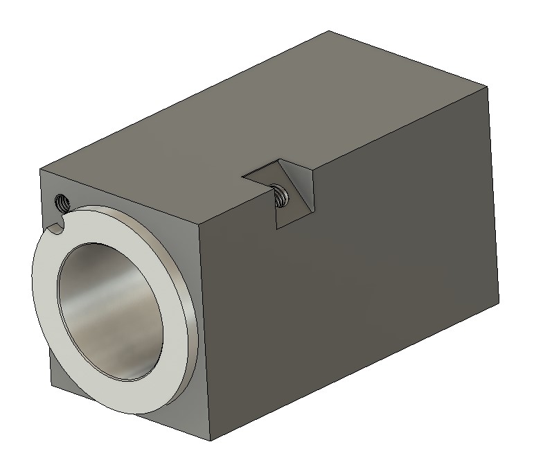
As an experiment I ran a new version of the block with a larger bore and then lined it with an aluminium sleeve that was a smooth fit on the shank.   I also turned a flange on the end of this sleeve so that the adjuster nut had a smooth metal surface to ride against.

The addition of the sleeve looks promising in solving these two issues.  I admit it is going against the concept of a 3D printed set of parts but the sleeve is easy to turn up on the lathe and the new block in PLA is still much easier to produce that trying to make the block totally in metal.

You can download the edited write up, new collet chuch holder block STEP and the sleeve drawing in this add on ZIP file.

Links to similar or related post are listed below : –

3D Printed Knob Variations

How I Create Robust 3D Printed Knobs

First of all an apology … colour has arrived as I have finally migrated to the WordPress Guttenberg editor from the Classic Editor. The Classic is due to be phased out in the near future so I thought I had better jump before I was pushed. I can see the advantages this offers but I am still getting to understand the different way of working.

That aside, onto the post …

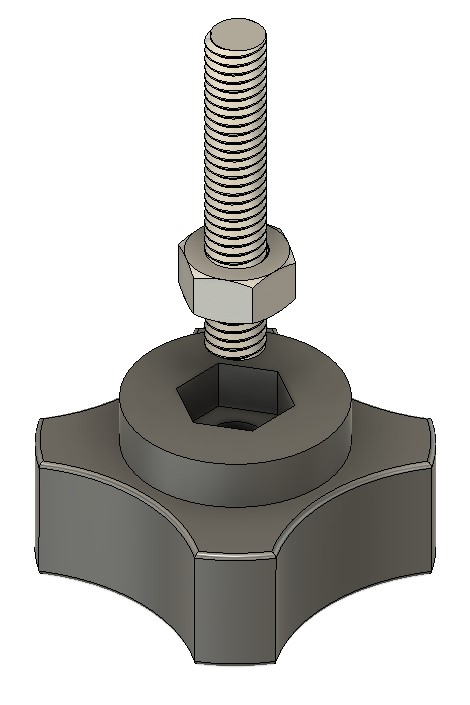
The problem with creating 3D knobs is that they can lack robustness unless they are made less dependent on the printed material. There are various ways round this but the easiest method I have found is to embed a conventional metal thread or nut combination. This allows you to be as stylish as you want with the shape of the knob while knowing that the core locking material is resilient to twisting.

A couple of good examples that I have produced recently are a replacement knob for holding the cover of my BK3 bandsaw in place and one to allow hand tightening of a U bolt clamp to a pipe.

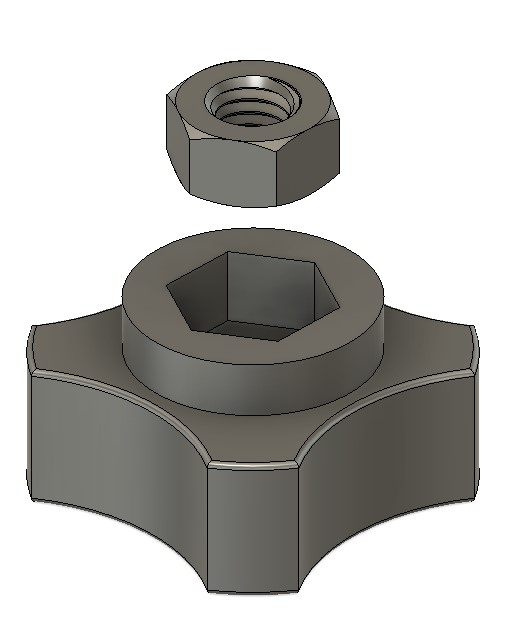
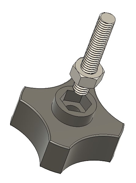
The BK3 clamp required a protruding thread (male) while the U bolt clamp needed a female style. Both were designed in Fusion 360 and embed either a nut or a thread and nut combination as the following images will show. The basic form of the knob is similar in that is has a cavity for the chosen nut size and for the female form may or may not have a through hole. The 3D printed body can be as fancy as you want to make it. I have been pleased with the basic shape shown below as it allows a firm grip to be applied.

Depending on how tight you can make the fit of the nut, the female form may need a dab of SuperGlue to hold the nut in place in the printed body and the male form will need Locktite on the thread and nut.

Female format
Male format

While both of the versions shown above have a boss for the nut cavity, this could equally be inset into the main body of the knob so it finishes flush. Next time you shorten a screw, save the thread offcut for future use on a knob.

Links to similar or related post are listed below : –

3D printed multiple punch holding tool using Fusion 360 Parameters

Using Fusion 360 Parameter Functions on this useful tool

I was pointed to this punch holder idea by a friend.  It was shown on HomeMadeTools.net and conceived by Andy Foale.   

Here is the link to the original post : –

https://www.homemadetools.net/forum/multiple-hand-stamp-helping-hand-65882

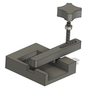
I thought it might be practical to make it as a 3D printed device and with a bit of guesswork came up with a first pass design in Fusion 360.   This was based on my set of punches which are 6.4mm square (1/4″) and 58mm long.   The design printed in PLA without any problems and the finished punch holder worked fine.  It uses one of my printed knobs as mentioned in another post.

3D printed punch holder per Andy Foales
Fusion 360 pictorial view of the finished punch holder

The success led to requests from others who liked the 3D print concept but had different size punches so needed the design tweaked to suit.

This looked like a good excuse to re-familiarise myself with Fusion 360s Parameter functions.   In short these allow you to program interrelated dimensions in a design through a series of basic algebraic functions.   The end result is a design that is fully flexible on the size of the punches to be used and the number of punches that might be judged needed as the maximum ‘word’ length.

The Fusion file is here in a ZIP file

punch holder v5

The Fusion file includes the holder, the clamping bar and the knob body.   You will need a short length of M6 threaded rod and a M6 nut to finish the knob.  The file is configured to 6mm punches, 63mm long but you can edit using Parameters function under Modify.  Clearly once you have the Fusion file you could run also run a CAM program and CNC cut the punch holder.

I am afraid this is a Fusion 360 file only.   If you aren’t a Fusion user (why not ??) and you want a STEP file creating to your punch sizes then email me and I can run it for you.

As stated in the original article, the kerning of the letters is defined by the punch cross section.

Similar or related subjects : –

Home made knobs without knurling

I always used to make customised knobs in metal which had a knurled body with a piece of studding screwed and Loctited in place.   It was good knurling practice and they looked fine until 3D printing came along.

I now have a variety of ‘styles’ for knob bodies modelled in Fusion 360.  These have a hexagonal profile recess together with either a threaded hole or  clearance hole modelled into them.   A nut is Loctited onto the thread and then the thread with the nut in place SuperGlued into the 3D printed body.

As usual I’m all for an easy (a.k.a. lazy) way of doing things …. here is a Fusion image.

3D printed knob
Fusion modelled image of a 3D printed knob

Similar or related subjects : –

Verified by ExactMetrics