A really useful plugin to give a colour highlighted listing
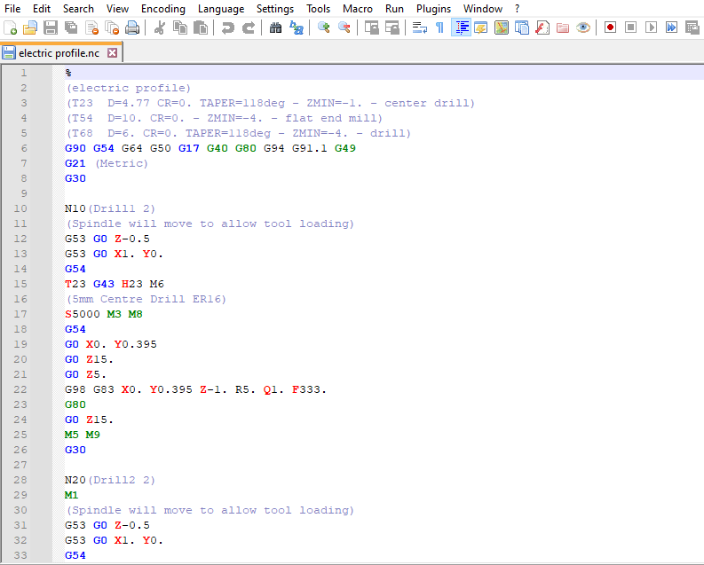
I am a great lover of Notepad ++ as a text editor. It has so many useful facilities and I particularly like it for checking Arduino code when frustration has set in ( …. so quite regularly …). The default inbuilt colour highlighting makes errors stand out as obvious clangs.
By chance I stumbled across a XML file plugin for Notepad ++ that is dedicated to its use when editing CAD/CAM GCode produced by design programs such as Fusion 360. Normally I would use GWizard Editor by CNC Workshop for editing such code as this also gives a graphical representation of the tool paths being created. The Notepad ++ plugin does not give the graphical image but there is an additional comment on the download post suggesting that this might also be available. See the following link to the post for the download and for further details.
This modification has worked very well … except when I want to use the height gauge off line when the PathPilot computer isn’t switched on. The level of frustration over the downside impact of this well intentioned modification was starting to irritate.
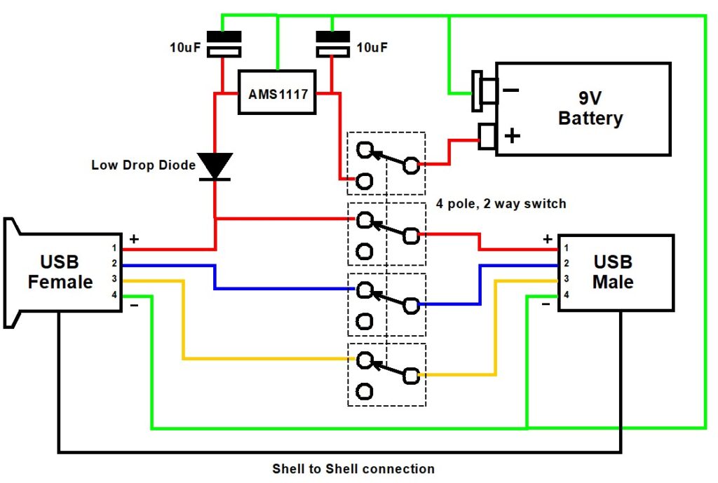
I had a male and female USB socket in stock along with a 4 pole 3 way rotary switch and a few AMS1117 low drop out 5V regulators. The rotary switch was one of those where you can move a selector pin to make it a 4 pole 2 way. A quick sketch and I think the problem is solved.
The logic is quite simple. Note that the colours used are just to make the diagram more easily understood and the colours chosen have no bearing on normal USB cabling colours.
In computer mode the wiring acts as a pass through connection for normal USB working. The computer is connected to the USB Male and the height gauge to the USB Female.
In ‘local’ mode the USB connections from the computer are all disconnected by the switch and power to the height gauge is provided instead by the 9V battery via the AMS1117 5V regulator and the isolating diode. Note the diode needs to be a low forward voltage device such as Schottky diode. It is not super critical as the regulator I fitted to the height gauge electronics box is a low voltage drop regulator. In total the current drawn in ‘local’ mode is around 10mA so the 9V battery will last a long time …. providing I don’t forget to switch it off (i.e. that is back to ‘computer’ mode). Which probably means I should fit a LED to the output of the AMS1117 to show the device is live on battery……
I built the device as a bird’s nest and 3D printed an enclosure. One less workshop frustration (hopefully).
One other thing to mention. The original write up detailed adding a 3V3 AMS1117 low drop out regulator to power the height gauge. See the link below.
If it is cold in the workshop the display on the height gauge can be a little dim to read. I have boosted the contrast by ‘jacking up’ the AMS1117 in the height gauge electronics box by adding a single Schottky low drop diode in the ground lead of the regulator. This increases the output voltage by the amount of the forward drop of the diode. To be clinical you should really add a tantalum capacitor across the diode to improve the stability of this modification.
Links to similar or related post are listed below : –
A good reason why not to leave a parallel on the way cover
I was running a milling job on my 440 the other day and I had left a parallel on the Y axis front way cover when I had switched off in the evening. Next morning I switched on and homed the axis in the usual order of X axis and then the Y only to hear a crunch as it reached the homing position. The parallel had got jammed under the table front shroud. I reversed the motion, removed the parallel, homed Z and carried on.
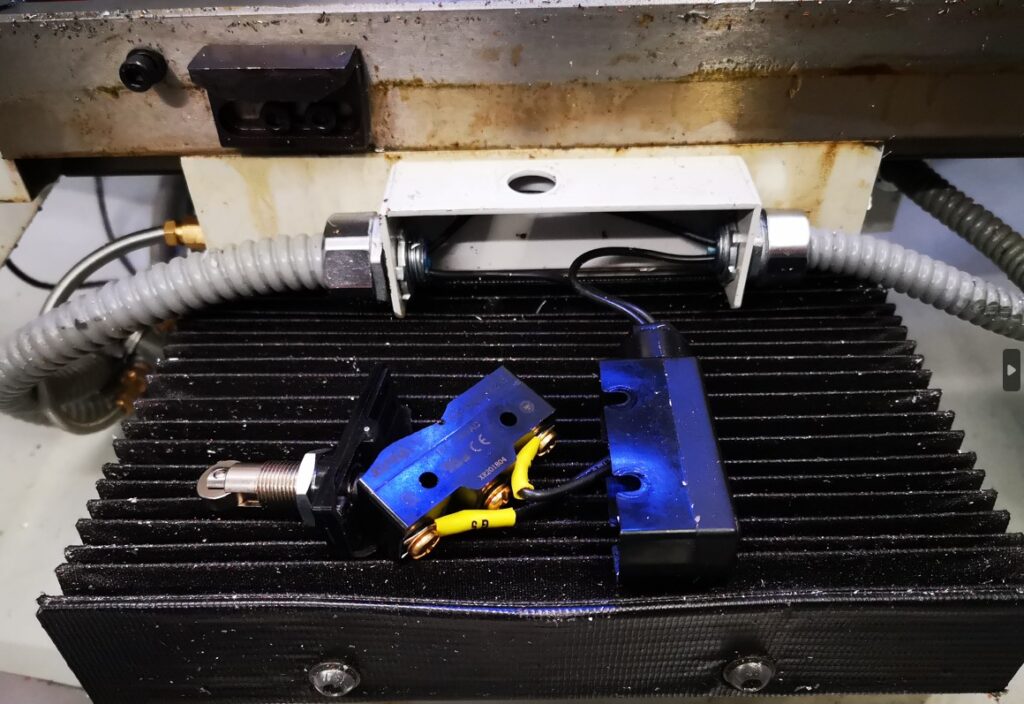
Fast forward to the next day. Switched on and homed X which resulted in a very bad end stop stepper chatter. I stopped the motion and moved the X axis back. Something bad had happened. I stripped off my machine vice and my tooling table and removed the table front cover. The limit switch had been crushed, presumably by the parallel the previous day.
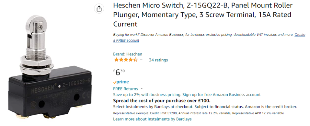
I’d like to say that this is the first time this has happened …. but it isn’t. (Hence the ding in the cover front edge …). A quick check on Amazon revealed quite a few identical looking replacement switches. There was also a twin pack available from China for much the same price but clearly much longer delivery time. A new switch was ordered and all is now up and running again (after re-tramming the tooling plate and then the mill vice etc etc …. what a pain ….)
In passing I do keep pondering the 440 limit switches and wondering if I could replace them with inductive sensors but it all looks a bit difficult having to sort out the additional wiring needed. Maybe another day ? (Sadly such a modification would still not stop me stupidly leaving things on the way cover ….)
Links to similar or related post are listed below : –
I had a recent request to machine some panels in 3mm thick ACM. This has a polyethylene core sandwiched and bonded between two thin sheets of aluminium. The sizes of the various panels requested could not be easily accommodated on my Tormach PCNC440 CNC mill so I had to dust off my CNCEST 3040T baby router. Five out of the six panels would fit inside the 3040 working footprint but the sixth required me to revert to a two setup movement of the workpiece in the Y axis. My write up of this stepping process for oversize objects can be read here.
The CNCEST 3040 has a maximum spindle speed of 10k RPM and is controlled using Mach3 with all the frustrations that brings to the party plus manual tool changes etc etc.
I received DXF drawings of the panels and these were imported into Fusion where they were simply extruded to 3mm before processing in Fusion Manufacturing. Each CAM operation was exported as a separate function into Mach3 regardless of tool changes. This gave me step by step control.
I used a 12mm thick MDF sacrificial (spoil) backing board to mount the panels. As all the panels were of the same general dimensions this made mounting the panels a repeatable process using a fixed matrix of woodscrews into the MDF. The 12mm depth of the mounting board made the tooling pin reference holes for the Y move much more rigidly fixed and as a result more repeatable to use.
The main problem encountered was that the ACM does not readily adapt to machining with conventional end mill cutters. I tried using my stock 2 flute parts and these would skim on the top aluminium surface while the plastic underneath deformed to the Z axis increasing pressure. Once sufficient pressure was exerted the tool would finally bite into the aluminium and punch through into the plastic with a noticeable ‘clunk’. This played all sorts of havoc with the Z axis height referencing and also lead at one stage to the Z axis stepper coupling working lose.
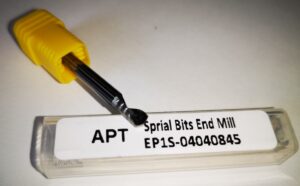
The solution was to go to a single flute spiral cutter style. These were purchased from APT Tools (UK supplier). Hot knife through butter comes to mind with the result of this change.
The single flute spiral end mill from APT Tooling UK
For straightforward hole cutting I used standard PCB carbide drill bits from Drill Services (UK supplier). These are nice to use as all have a standard 1/8″ shank which makes tool changing a little bit easier.
Once all these frustrations were overcome the process became much more repeatable albeit with one or two curved balls due to Mach3 lock ups. Have you ever enjoyed trying to manually re-reference a half finished job ? …..
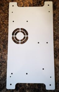
The finished largest panel that required a two step movement in Y axis
More accumulated knowledge gained and lots of black plastic swarf (chips) to clean up before it could migrate everywhere into the house.
When I bought my Tormach PCNC440 in 2016 I included the enclosure kit in my order. On receipt I thought that fitting the enclosure would dominate the size of the workshop so I never got round to fitting it. It has sat in its shipping box since then. I have consequently shared quite a bit of my swarf (chips) with long suffering family.
After a recent (particularly heavy) CNC run I had a serious covering of swarf in the machine tray and because I had no enclosure round the mill, I had quite a lot distributed further afield (i.e. into the house). Domestic peace was becoming an issue. Time to do something about it.
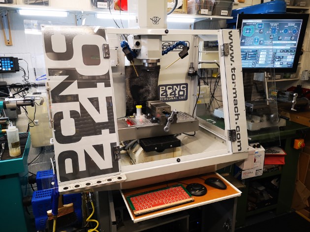
Out came the enclosure kit, cobwebs dusted off and around three hours later I had the enclosure fitted. I have to say it looks good and does not overpower the workshop as I thought it would. My wife is impressed and says it looks a more professional machine and ‘if you had it why didn’t you fit it before now’ ?
The picture above shows the enclosure mounted on my PCNC440 with the monitor in the original position before fitting the extension arm to the ISO bracket. The keyboard tray uses a domestic drawer rail mounted on the top of the standard Tormach cabinet. My recently fitted dual fogbuster system and my Hall Effect based tool height setter (yellow top) are visible.
The fitting did however create some follow up problems.
My control monitor had up to now been mounted on the side of the 440 on a standard ISO TV mount. With the enclosure fitted this meant it was ’round the side’ and difficult to get to. I debated a new long reach ISO but they are expensive. Plan B was to make something. I rummaged around in my aluminium stock and with the help of Fusion 360 came up with a seriously overengineered extension arm to add to the existing ISO mount. This would allow the monitor to move forward to be in reach at the front of the mill.
My seriously over engineered extension bracket to move the ISO mounting of the monitor more to the front of the 440
This bracket became the first CNC job to run after fitting the enclosure. I am pleased to say it was the cleanest my workshop floor had ever been after running a job.
Having fitted the new bracket and mounted the monitor, all the cables needed extending. Fortunately I had had the foresight on my original order to include the extension cable kit. As a result I only had to extend the power supply lead from the monitor 12V ‘brick’ supply.
The second issue was where to mount my ITTP probe as this had formerly mounted on the side of the 440. With help of some more Fusion design I modelled a corner mount that picked up on the enclosure fastenings.
After that first heavy machining run I noticed for the first time the slight smell of the mist coolant when opening the enclosure doors. Before the enclosure was fitted the smell must have dispersed into the general workshop air. With the enclosure fitted the air was concentrated inside the mill and I only got the smell when sticking my head inside. While it had never been a problem (as far as I can tell …) I thought I should do something about it.
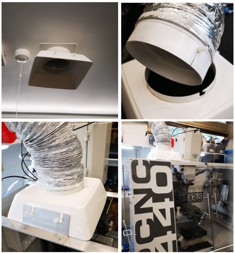
Sometime ago I installed a ceiling extract duct in the workshop. This vents to the outside world via a custom roof tile. Normally the system sits with a flared cowling (made from a cut down flower pot) on the ceiling entry duct. The system normally acts as a background trickle extract. The cunning plan in the design was to use various pipe components to provide bayonet style connection pins (Nylon screws) to allow extension trunking to be used. A bit like a BNC RF connector if this is familiar to you. This would allow me to use an add-on length of expanding flexi trunking to bring the extract nearer to any heavy fumy activity such as welding or oil bath hardening.
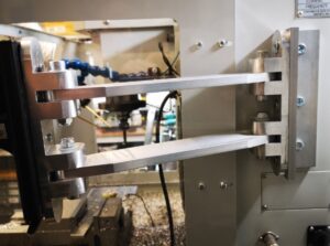
With the use of further scrap odds and ends of aluminium, I mounted a pair of support bars across the top of the new 440 enclosure. These would fix the ducting over the enclosure during heaving CNC sessions. Not a total solution but certainly one that will reduce the general smell of XtremeCut 250C when I stick my head in the enclosure.
Extract system showing ceiling mounting intake, trunking adapter and mounting on my Tormach PCNC440. Note the two Nylon screw protrusions are for a bench mounting clamp when used for welding extraction etc and now used on this new use of the system on the mill.
A good day’s activity with all the issues addressed and domestic bliss hopefully restored.