CNC Work Reference Centring using Mushrooms

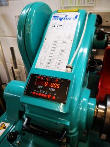
This is probably not original but worth commenting on.   I have a tooling plate on the bed of my Tormach PCNC440.  This has a matrix of M8 holes on 25mm spacing together with intermediate 3.7mm tooling pin holes.

Quite often I have a need to set up my work CNC coordinate system (WCS) such that it is centred on one of the M8 holes. 

If I want to do a quick and dirty centre on one of these holes then I use the Laser Centring tool as mentioned elsewhere on my blog.

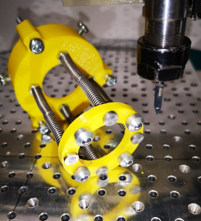
If I need to be a bit more precise then I have a mushroom/top hat shaped disc with shank that is a tight fit in the tapped M8 holes.  PathPilot has a number of probing routines and these include finding the centre of a circular object.    Simply push the top hat into the desired hole and then probe the disc for centre.  You can use an active probe such as the Hallmark ITTP.

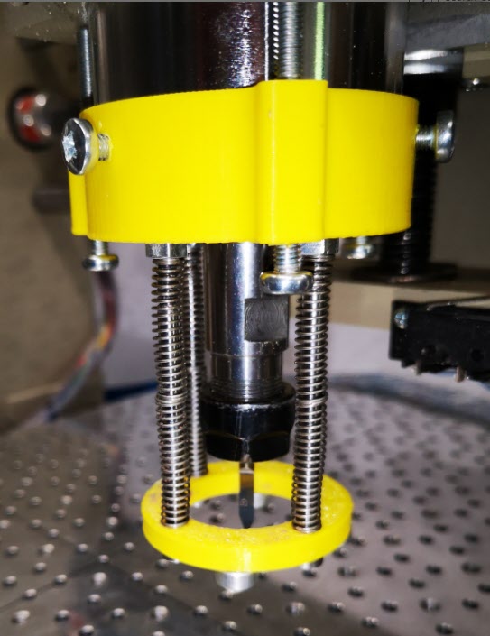
If you haven’t got an active probe you can use a Haimer.   Simply align the Haimer tip somewhere close to a maximum point on the disc circumference and advance the axis to show a reading on the Haimer.  Rock the opposite axis back and forth and watch the Haimer reading to find the high point on the circumference.   Zero the axis.   Go to the opposite side of the disc and repeat this process and divide the measured diameter by 2 for the disc centre.   Repeat on the opposite axis.

(You can use this Haimer rocking back and forth method to find the diameter high point when cross drilling a circular item to fit grub screws etc).

Hole centring mushrooms
Two examples from my ‘mushroom farm’

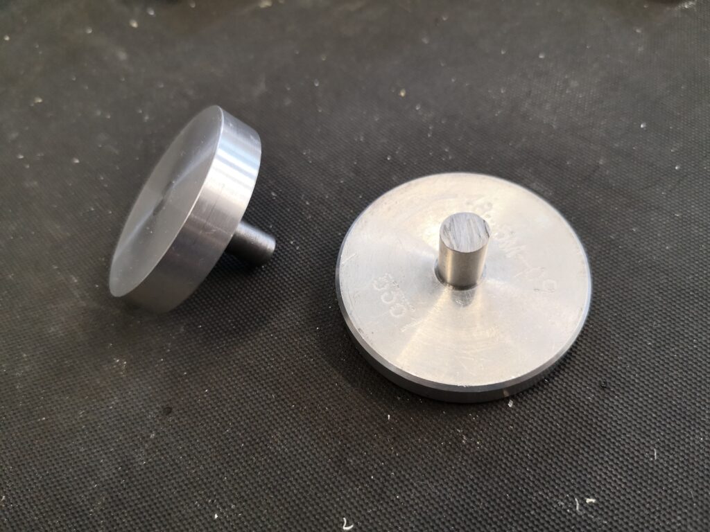
The mushrooms are made with a silver steel shank that is skimmed to be a non wobble (how technical is that ..) fit in M8 (~6.8mm) and an aluminium top hat that is superglued in place on the shank.   Once the glue has set the top hat is squared up while held in a collet in the lathe.  This ensures concentricity with the shank.   The disc will now sit flat to the tooling table when the shank is pressed home and perpendicular in the hole.

Clearly the larger the disc diameter the less centring error there will be.

I now have a ‘mushroom farm’ of discs for all manner of hole sizes.  It’s not rocket science but as you well know, I am all for a simple (aka lazy) approach.  Apologies to all the Grannies out there.

Similar or related subjects : –

Clough42 Electronic Leadscrew Project Implementation Notes

I have been avidly watching Clough42 on YouTube.  James comes over as a really nice guy and his presentation of his projects is excellent.

My principle interest is the Electronic Leadscrew modification to lathes.  When installed this removes all the hassle of gearboxes and look up tables to be able to cut both Imperial and Metric screw threads and to set X axis movement feed rates.

The concept is simple but his implementation is second to none.  A rotary encoder is fitted to the spindle to count revolutions of the chuck and a stepper motor (or servo hybrid) controls the rotation of the leadscrew.  The resulting feed speed is derived from look up tables.  The whole installation is controlled by a Texas Instruments LaunchPad C2000 microcontroller development board.

I have documented how I implemented this on my Myford Super 7 Big Bore lathe and the pdf can be downloaded below.   There is also a ZIP file of all the Fusion related models for either CNC or 3D printing.

Electronic Leadscrew on Myford Super 7

Minor edits added to v3 relating to programming the servo controller

Electronic Leadscrew on Myford Super 7 v3

Electronic Leadscrew Fusion 360 Files

Updates : –

Painted control panel for Clough42 Electronic Leadscrew
Finally got the Clough42 Electronic Leadscrew control panel box painted and rather pleased with the result.

Since installing the ELS I have incorporated thrust bearings on the leadscrew mounting.   This impacts on the coupling to the stepper motor.

Similar or related subjects : –

Floating pressure foot for the CNCEST3040T mini milling machine

A new idea for keeping PCB material flat while milling artworks

The vacuum plate mentioned elsewhere on my blog serves me well when milling printed circuit boards on the Tormach PCNC440.   It keeps the PCB material flat and makes the cut widths repeatable when using V cutters.

The plate cannot be easily used on my CNCEST3040 due to the restricted Z height.   We have experimented with various techniques to keep the PCB material clamped flat on the smaller mill with varying degrees of success.

Idle hands and brain during social distancing has produced a possible solution that might be of interest and stimulation to others.   It consists of a circular pressure ring that sits around the spindle chuck and tool.   There is a second ring that sits on the spindle body connected to the lower ring with rods which have coaxial springs pushing down on the lower ring.   The magic is to use mini ball transfer units on the lower ring to press down on the PCB and glide friction free around the PCB as the cutter does its stuff.  The assembly is held in place on the spindle with 3 gripping screws.   The downward pressure is adjusted by 3 screws that press against the spindle mounting frame.

The ball transfer units come in all sizes and are very common in baggage handling systems at airports and in industrial conveyor systems.  The ones I used came from RS and have a 4.8mm ball and a M2 mounting shank

The prototype was made using 3D printed rings.   There is an image below.  Apologies for the yellow PLA but finding any PLA at a decent price is very difficult in the present circumstances.

Bottom view of pressure foot for CNCEST3040
A view of the underside of the lower ring and the four ball transfer units. In the background is the upper ring that sits around the spindle with the pressure adjusting screws and the spindle gripping screws.
Pressure foot for the CNCEST3040 in place on the spindle
View of the pressure foot in place on the spindle showing the tension adjusting screws and spindle grip screws

The idea seems to work and has produced some good consistent quality PCB prints.   It does have disadvantages in that you need to have a larger PCB blank to allow for the larger footprint of the pressure ring.   It is probably only of practical use for PCB milling but then the problem of flatness is less critical in drilling the board and routing the profile.

Similar or related subjects : –

Probes and Haimer Taster Modification

I have been using a Wildhorse Innovation CNC set up probe for some time now.  It works OK but sometimes the results are not consistent.   After one frustration session I decided to upgrade it to the Hallmark ITTP probe from Threadexpress in New Zealand.  

It arrived today after nearly a month in transit due to the current lock down restrictions.  On opening the package I was impressed with the quality of the engineering.  It is a nice device.  It uses the usual 3 pronged contact mechanism.   Supplied with the probe is a tube of grease that helps protect the contact reliability.  The interface cable has a 5 pin DIN that plugs into the Tormach expansion socket and the shank is a standard TTS compatible size.

hallmark ittp cnc probe mounted on the tormach pcnc440
The Hallmark ITTP probe mounted in the Tormach ready for setup and testing.  You can also see my angel ring light illuminator and Hall Effect tool height setter.

I ran through the initial preparatory procedure and then loaded it into the Tormach 440 spindle.   Pathpilot has a number of excellent set up routines to adjust the probe and make measurements.  One of these, the Effective Tip Diameter is quite critical.  All this went to plan and very quickly.  Some initial probing gave repeatable and accurate results so first impressions are good.  

Some of the Tormach PathPilot CNC probing routines
PathPilot probe setup screen and the two probing routine screens.

I’ll give some updates as the probe gets pressed into service but my first impressions are good with repeatable accurate readings.  

In the course of checking out the ITTP probe I needed a reference cross check on the various setup measurements.   My Haimer Taster seemed a bit erratic and on inspection I discovered the axial shank holding bolt had worked lose.  This meant a re-calibration of the eccentricity of the probe point would be needed.  

The alignment process involves adjustment of four grub screws in the shank body.  These tweak the ’tilt’ of the shank to get a concentric rotation of the probe ball point.   As there are four screws I use two hex Allen keys to make the adjustments to each in line pair.  This is quicker than with a single hex key being swapped from side to side.  It is a bit like the process I use when centring a 4 jaw chuck. The adjustment is done against a dial gauge riding against the probe ball point.   Once you get the knack this process doesn’t usually take too long using the two key method.   

The frustration is that the Allen keys provided with the Haimer are a bit chocolate based and the ends chew up easily.  The result is you tighten a grub screw and the hex key end twists and gets jammed into the hex socket in the grub screw.   While trying to waggle the jammed key you mess up your carefully made adjustment.  Aaaargh !

I ground back the worn end of the Allen keys to clean up the hex profile but they quickly degraded.   In the end I took the grub screws out completely and replaced them with some M4 cap head bolts.   Joyful !

adjusting screw change on Haimer Taster concentricity adjustment
How ugly is this ? Replacement screws on my Haimer Taster

Yes I know it doesn’t look pretty but it is now a real pleasure to make the adjustments with a couple of larger T wrenches.  It is probably a criminal thing to do to such a lovely instrument but life is too short.

Next job will be to modify the arrangement of my tool sharing junction box on the Tormach expansion port so my Hall Effect tool height setter and the ITTP can share the input.

Similar or related subjects : –

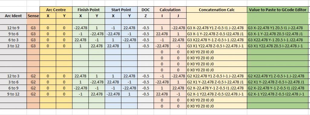
Arc and Circle I and J code calculator for GCode cutting paths

I & J Arc Code Calculator (with updated spreadsheet)

I had a need to hard code a circular PCB cut out CNC code that would cut four arcs around a milled PCB and leave four breakout tabs to retain the board in place in the blank until the job was finished.

To create I & J codes you need to know the start point, end point and radius of the arc.   The end point becomes the X and Y.  The  delta X and Y location relative to the radius centre point X and Y becomes the I and J values.   You can also add a depth of cut value for Z as part of the block.  Note that the Arc is assumed to run anticlockwise when using a G3 code running from start point to finish point.   Use G2 if you want a clockwise motion.   The principle is the same with both rotations.

You end up with a block code of the format G3 (G2) Xa Yb Zc Id Je where a,b,c,d,e are the coordinate values.  I found that working with positive and negative values when trying to find the I and J values relative to the centre was hurting my brain.   A spreadsheet was needed …..

Screen shot of I and J calculator spreadsheet
Screen shot of I and J calculator spreadsheet for G2 and G3 coding with examples based on CW and ACW arcs around quarters of a circle with small gaps between each arc.


You can download the sheet as a ZIP file from the link below.

Arc and Circle Calculation Sheet for GCode

Similar or related subjects : –

Verified by ExactMetrics