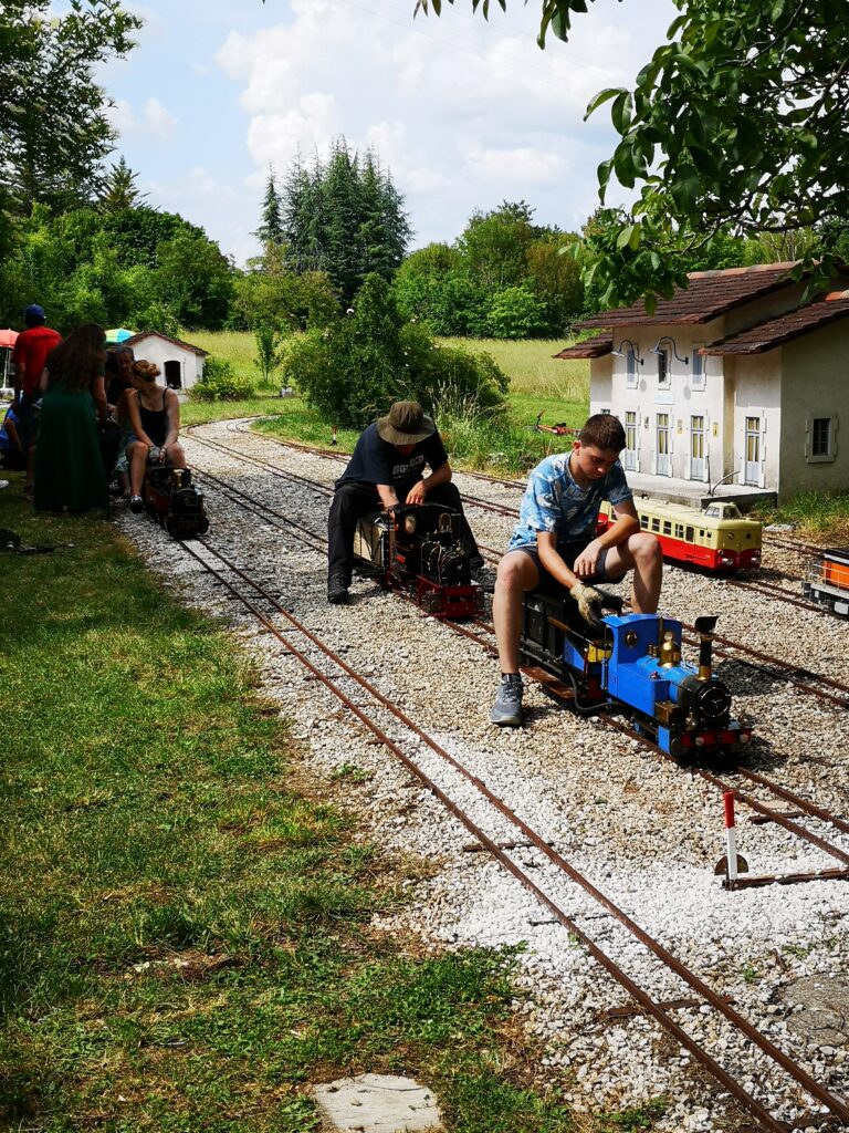
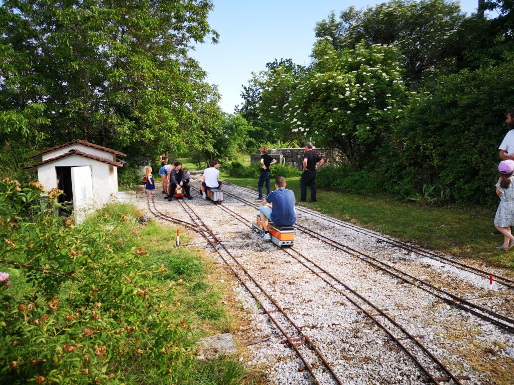
We were very lucky to be invited to this event near Cahors. A significant number of the engines were Polly designs and the owner of the track has had a long standing relationship with Polly Model Engineering.
The track has two loops and a very significant incline which tested not just the engines but also the drivers. One very encouraging aspect of the weekend was the number of young people, both male and female who were enjoying driving the track.
Links to similar or related post are listed below : –
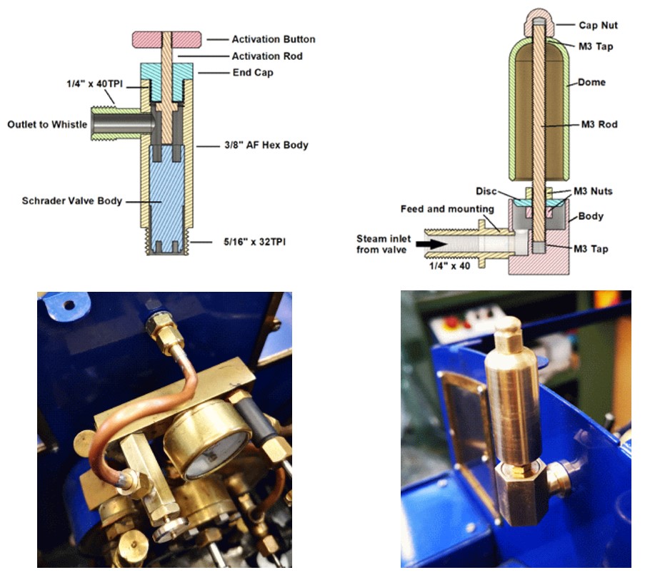
It had become a standing family joke on steaming outings that my Polly V whistle left a lot to be desired. Quite often it would do nothing more than a feeble splutter. The Polly V kit supplied whistle is fitted under the running board on the left hand side of the cab. The pipe run is long and somewhat tortuous. I had insulated the pipe to reduce feed loss but this made little difference. The whistle valve also had a gentle leak and was very stiff to activate. All in all not a good setup.
A recent article in Engineering In Miniature (EIM) by Richard Wightman (September 2022) went into detail about a whistle and valve combination he had created. The whistle was fairly conventional but very compact. The steam control valve was unusual in that he used a standard tyre Schrader valve. This tweaked my interest and I set about upgrading my Polly V locomotive using this technique. Here are some Fusion 360 images and shots of the new valve and whistle mounted in place on my Polly V.
Here is a blow by blow description of the process as a PDF download.
Last Sunday was a members steaming day at the model club. I told all the family I would be there and to bring the grandchildren along for a ride.
I arrived early with a view to getting steam up and be ready to go … in theory.
First problem was that the connecting rods had stopped in a position that was blocking fitting the fire tray holding pin. This immediately got worse in that the cylinders had seized since my last run. The more experienced members told me not to worry and if I could move the wheels enough then fit the fire tray and get things warmed up. After some rocking I managed this slight movement …. but forgot I hadn’t filled the boiler and the fire was burning very brightly. Mad panic to get some water in quickly.
Steam pressure up to 90psi but no joy on the cylinders. Gentle tapping on the con rods lead to heavy tapping on the con rods and lots of slide dragging back and forth on the steaming bay. Still no joy. Cylinders locked.
Now running out of water in the boiler. Grandchildren arrived. “Why can’t we have a ride grandddad ?”. Grabbed the handpump leaver and rapidly pumped away to get water into the boiler …. too rapidly in fact and broke my hand pump leaver. Still had a few PSI of pressure and thankfully the injector kicked in … for a short while until the pressure dropped.
How bad can this get ?
Some slight movement on the cylinders now. Grabbed some blocks of wood and got the engine airborne so the axle pump could be used … if I could just get the wheels to fully turn. More tapping/thrashing at the con rods and suddenly the wheels jumped into motion. Phew. Water now flowing into the boiler, fire good, pressure good. Get out on the track quick and keep the grandchildren quiet.
Back home in the workshop I made a new hand pump handle and fitted new oil port plugs on the top of each cylinder each with a M3 feed hole. This means I can syringe oil into the valve and cylinders a lot more easily after future steamings.
It is a hobby after all but this was one of the most stressful steamings I have ever experienced – all because I was in a rush last time out and did not do the end of day drain down processes correctly because it was tipping down with rain. Lesson learned. Thankfully no long term damage to the cylinders.
This post was corrupted when converting from Classic Editor to the new Block Editor and has been re-created.
I have made mention of my Poly V 5″ gauge live steam locomotive elsewhere on my blog. With lockdown having restricted running the engine on the Club track, the loco has sat idle in the workshop.
The locomotive has always been a struggle to maintain steam over a full running day. It starts off enthusiastically but then begins to struggle. This is frustrating and also embarrassing when I have to push it round to the steaming bay.
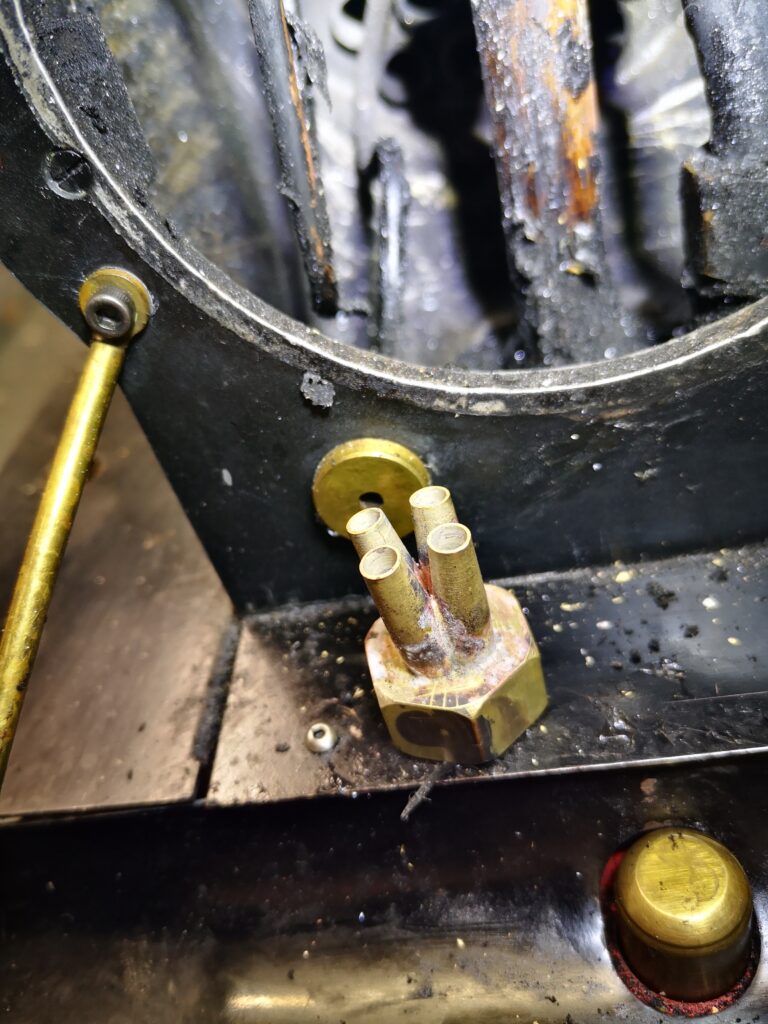
I was sent some notes on Lempor Draughting to change the blast characteristics in the smoke box. With time on my hands I spent some time on Fusion 360 drawing up a possible Lempor assembly. This is shown below. It consists of four nozzles each having a cumulative aperture area equal to the original blast nozzle as fitted in the Poly V.
The assembly was quite tricky. I bought in a new standard nozzle from Poly and then modelled it and the new sub nozzles in Fusion 360 to create the toolpath to mill out on the CNC, The new nozzles were created on the lathe and the mating butt flats machined on them in the mill. It was very fiddly. I wired them together and silver soldered them in place. Here is a picture of the finished assembly before fitting.
Because the new blast is diverging I had to increase the height of the petticoat. I did this experimentally by fitting a small grub screw at the back of the smoke stack to grip the petticoat as I moved it up and down. This resulted in the petticoat being almost at its maximum height. One idea suggested by a club member was to make this adjustment on a cold morning with the smoke box door open so you can see the blast pattern.
My subjective conclusion is that the engine now steams from cold much quicker and it runs very well (providing I keep the fire level high in the firebox….). Whether this is the new blast pipe or the Rosebud grate or the coal or a combination of all three is difficult to judge. It is certainly a different engine and a pleasure to drive.
Links to similar or related post are listed below : –
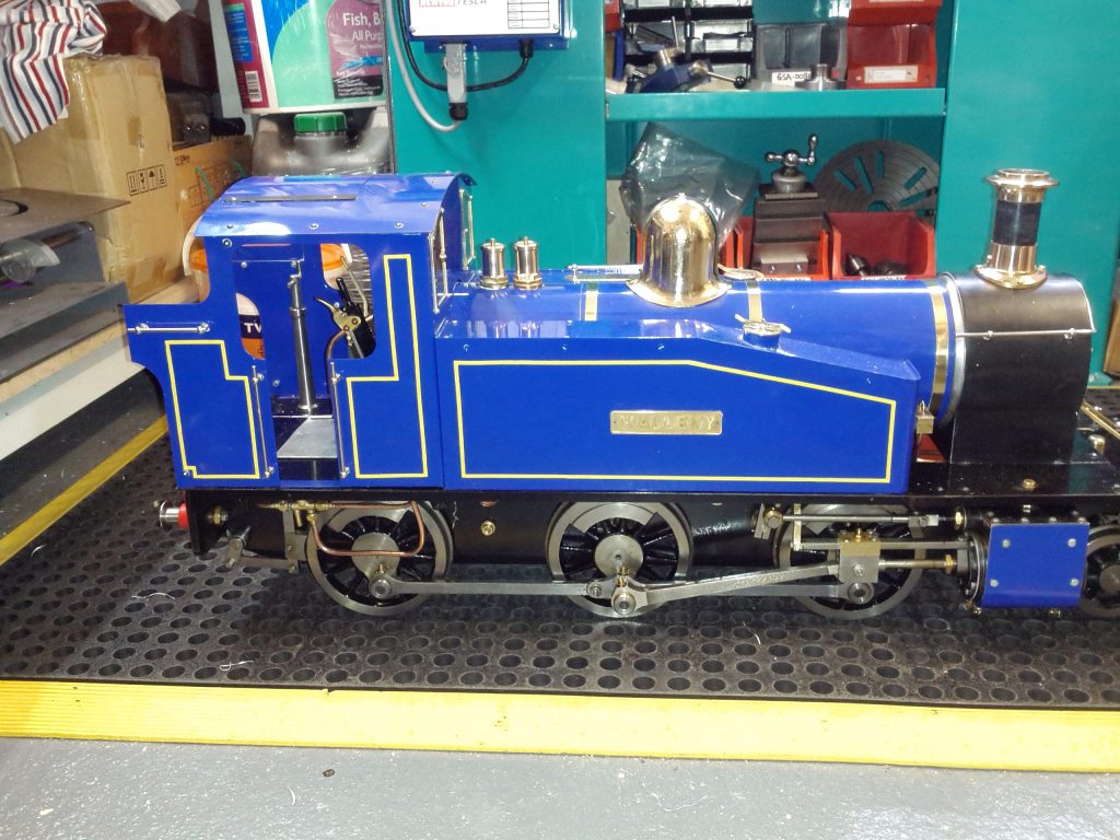
I have been the owner of a Polly V 5″ gauge locomotive for some time now. It has run OK but I have always had some unexplained happenings with it. Things like being reluctant to start and sounding ‘out of balance’ to use a clock making term. I also admit that while I know the overview of how it works I have never got to grips with Stephenson Valve Gear. I decided that some investigation was needed.
New Piston Rings
A bought a new pair of O rings for the cylinders a few weeks ago and decided it was time to fit these as a first step in an engine health check. This was easier to do than I expected. The end face of each cylinder is held in place with eight hex head screws and when these are removed the end plate can be taken off. The cylinder rod can be disconnected and the piston pushed out of the end sufficiently to swap out the O rings. A liberal coating of silicon grease on the new O ring allows the piston to be gently squeezed back into the cylinder and job done. Having completed this exercise I was feeling a bit more confident.
The Stephenson Link
Out of curiosity I decided to have a look inside the valve chests on top of the cylinders. These were a bit more fiddly to get at as I had to remove some of the chassis work but not a major problem. On the bottom face of each valve chamber are two slots. These slots allow steam in and out / to and from the piston cylinder. The timing block moves back and forth across these openings to alternately allow steam in and out of the piston chamber. The movement of the block is controlled by mechanical linkage and each cylinder is out of phase with the other to balance the drive to the wheels.
Having opened the two chests I noticed that both looked to be set up in a different way and as I rolled the engine up and down on the bench the openings in the bottom face of the chest were not revealed in a synchronised manner. Some investigation was needed.
When I bought the engine I also got a full set of the construction notes supplied with it from which the previous owner assembled it from new. I found these notes difficult to follow which was due to the fact that I was not conversant with the names of the individual parts mentioned. I stuck with it and the first thing that struck me as wrong was the gap at the end of the Stephenson Link was not the same in ‘Forward’ and ‘Reverse’ settings on the quadrant reverser. I had no idea why this was important and no idea of this was an absolute gap size that was needed (an actual measured distance) or just a relative similar size. Clearly it was not either of these and I needed to adjust it.
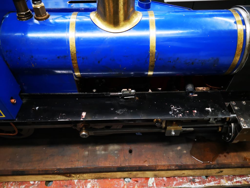
Much gloom followed as I realised the adjustment for this was behind the side water tank. This would have to come off. This looked fairly straightforward except the injector water feed is coupled into this tank in the cab area. The gland nut holding this is inside the water tank and a real pain to unfasten. The amount of arc that is possible to apply to the nut is very restricted. Eventually I managed to free this and the tank came away to reveal the quadrant rod adjuster. It was then a two minute job to adjust the quadrant rod length to balance up the end gaps on the Stephenson link in Forward and Reverse.
View showing side tank removed and the quadrant rod adjuster
Timing the Valve Gear
Having balanced the Stephenson Link, the next step was to adjust the valve blocks. I put the quadrant reverser at its Centre position and rolled the engine up and down on the bench watching each valve block move. The movement of each block was not symmetrical . In the Centre position the block should only just move a small amount back and forth to just reveal the two port openings in the base of the chamber.
This is easy to adjust by removing the valve actuating link arm screw. After some back and form adjusting I got the blocks to achieve the minimal movement needed about the centre position.
If I now rolled the engine back and forth on the bench in ‘Forward’ or ‘Reverse’ the movement of the blocks increased to reveal the full area of the two ports and with each side of the engine leading in turn. I now had a nice action of the valve blocks alternately opening and closing over the front and back ports with no excessive movement. Things looked much better. I cleaned up the valve chamber lid and fitted a new gasket to each chamber. I put the engine on the rolling road and using compressed air ran the engine up. Wonderful ! It now sounded more balanced and was much happier to start in Forward or Backwards. Here is a pictorial representation of the valve action.
Without the balancing in the Stephenson Link this would not have been possible to achieve.
The Eccentrics
While delving around on the underside I noticed that one of the eccentrics had movement on it and the eccentric arms were sloppy. On the Polly kit the eccentrics are positioned with a grub screw into pre-drilled holes on the axle.
Another major gloom session ensued as it looked at first sight that the boiler would have to come off to work on the eccentric arms. However after playing with positioning of the eccentrics I found I could get the clamping screws out, drop the arms off and so allow tightening of the grub screws. In the process of doing this I found that there were tiny packing pieces between the faces of the eccentric arm halves. Clearly the original owner must have believed the eccentric arms were too tight and had packed them out. I did a trial fit without the packing and the eccentrics ran freely. Perhaps this had been done as a running in adjustment. On completion I did a second run on compressed air with no obvious issues.
Putting it back together
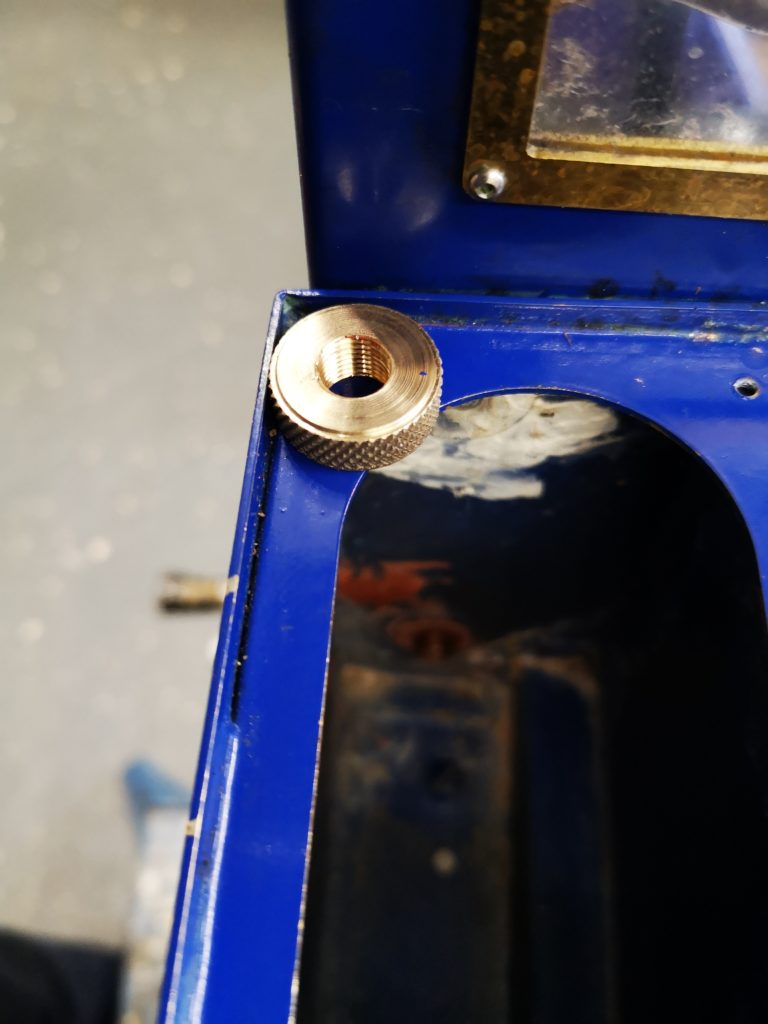
Re-assembling the chassis work was straightforward except replacing the side tank water feed to the injector. The original nut had been mangled by the previous owner so needed replacing. Rather than just fitting another hex nut I made a brass knurled nut. In the confines of the side tank this gave me better grip with my finger ends to tighten the fitting. Once it was finger tight I could use the end of a screwdriver to increment it tighter using the knurling surface to give me purchase.
Replacement knurled nut to fasten the injector water feed into the side tank
Other work
While having grease embedded under my finger nails I did a few other jobs on the engine.
The whistle valve had always leaked steam and I had bought in a new version of this with a stronger spring action. This was fitted along with a new steam valve feeding the injector.
I re-positioned the pressure gauge to be central in the cab rather than off to one side as originally fitted.
I fitted a new set of drain cocks on the cylinders.
Finally I adjusted the cylinder lubricator which had been a bit too liberal with its feed delivering a snotty chimney edge and a fine mist of oil to my face while driving. The adjustment screw was unlocked and moved back a small amount.
All back together and a good days work. A lot learned which is always a bonus and less fear of the black art of steam engines.
The next day I took the engine down to the club track and made quite a few circuits on the raised level track. The engine sounded and ran quite differently. It ran much better on lower levels of steam pressure. I also did not get a bath of lubricating oil but judging by the edge of the chimney there was still sufficient being passed into the cylinders.