A rite of passage ?
You may have watched James at Clough42 and Brandon at Inheritance Machining both make the Hemmingway Sensitive Knurling Tool (HK# 1115) and shared their experiences. In the past I have made a few Hemmingway kits and always enjoyed making them and the associated learning process. I decided to add the knurling tool to my collection.
Like James and Brandon I found the drawings beautifully presented but a little dyslexic with imperial dimensions showing as a mix of fractional and decimal units accompanied by metric equivalents. To get more intimate with the design and to circumvent the fraction and decimal imperial dimension issue I resorted to redrawing the design in Fusion 360. Fusion lets you set an overall dimension standard for a drawing but you can enter an individual dimension in any format or standard. Fusion will then display the individual dimension at the default drawing standard. This allows you to enter any dimension in mm, fractional Imperial or decimal Imperial. I find this a convenient way to better interpret the Hemmingway drawings. Redrawing in Fusion also highlights the potential problems in the rounding of metric dimensions from the imperial entries.
James and Brandon both resorted to traditional methods for the construction. This involved using a rotary table for the curves (of which there are many on the two jaws). I will now add further to my reputation of being a lazy engineer. Having redrawn the design in Fusion it was a logical step to produce the kit with CNC assistance.
While CNC might make the construction appear easier, it still creates headaches on work holding. This is magnified by the fact that the kit is supplied with ‘final size’ material. Brandon took this further by skimming all the supplied stock but then fell foul of the subsequent impact of this on some parts.
The CNC machining of the side plates, jaws, adjuster plates, spacer block and mounting block all went well to my CAM processes. This required sacrificial mounting plates and lots of checking before hitting ‘GO’. I am pleased and relieved to report no dings resulted from the CAM.
The majority of the remaining parts are lathe activities with, where needed, a liberal use of a collet block for cross drilling . I cheated on the adjuster thread and used M8 threaded rod with appropriate dimension changes to its mating components.
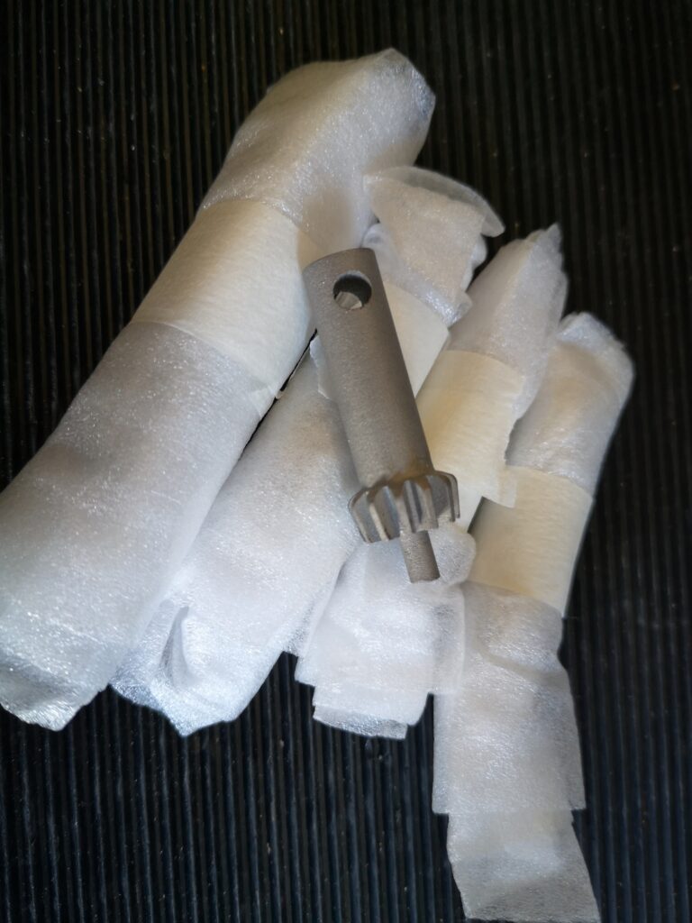
I had one post CNC ding on the lower jaw leading to an additional M3 hole. The lower jaw nut was the most probably the most tricky part. That aside all went to plan.
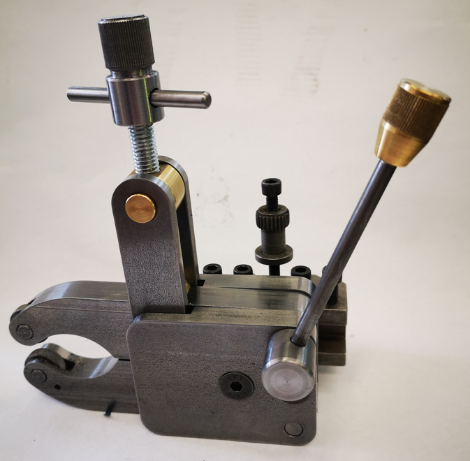
I used the semi finished tool to knurl the adjuster knob and pressure lever knob and was very pleased with the clean knurls that resulted. Here is my finished knurling kit mounted on a Myford QCTP holder.
Would I recommend the kit ? Yes – but it has some slightly advanced activity needing careful planning and thinking. The drawing dimensioning can catch you out. I think redrawing in Fusion helped highlight and clarify these issues. Measure twice and cut once is the order of the day particularly with respect to shaping the jaws. If you have CNC then this is a much easier way to go once you have got your head round the necessary work holding.
Note – the kit does not contain the knurling wheels so you need to order them separately.
Overall this has been an interesting and challenging project. I now have a very useful asset added to my workshop tooling.
Links to similar or related post are listed below : –
- Small handheld vacuum cleaner
- Eccentric Engineering Turnado freehand turning tool
- Rotring 300 2mm clutch pencil modification
- Kindling Cracker – a safer option
- SINO SDS2MS DRO repair
- A useful Amazon sourced small item storage system
- 3D Printed Threads Modelled in Fusion 360
- Three axis stepper controller PCB in stock
- Myford Super 7 Large Bore depth stop
- Tangential Lathe Toolholder for Myford Super 7