An alternative Bull’s Foot file for clock plate smoothing

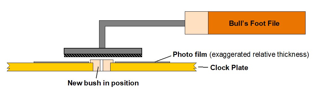
A Bull’s Foot file comes in various formats.  In its simplest form it is a small circular filing surface mounted at right angles to a handle.  Its common use is for making good after a clock plate has been re-bushed when there is a need to selectively finish the newly inserted bush material to be flush with the plate surface.  

The commercially made files sometimes have a curved lower surface or have a periphery ring or bordering parallel strips of metal to ensure that the filing action cannot go deeper than the existing plate surface level.  Without this the filing action would lead to unwanted scratching and disfigurement of the plate.

I have got around the commercial geometry by using a homemade flat filing surface with two protective spacing mediums.  To get quickly to somewhere near flush I use a piece of 35mm film (5 thou thickness) with a suitable hole punched in it glued or held over the bush. This protects the plate from a wider area of damage caused by my flat homemade Bull’s Foot.  There is graphical representation of the concept below.  This is a method suggested by William Smith and John Wilding in their various books.  If I want to get even closer to the plate surface I have some sticky backed shim material that is 1.2 thou thick that I stick around the bush.

Graphical representation of a Bull's Foot file in use

With the commercial items, the bush is filed until flush using an increasing finer grade abrasion on the Bull’s Foot disc.   This means having to have a number of different abrasive Bull’s Foot files.   These are unusually difficult to source and expensive to accumulate.

My solution to this is to have a few Bull’s foot metal ‘blanks’ to which I mount appropriate circles of different grades of wet and dry paper.   The chosen wet and dry is simply held in place on the ‘foot’ with double sided tape.

Homemade Bull's Foot files
Homemade Bull’s Foot files and handles

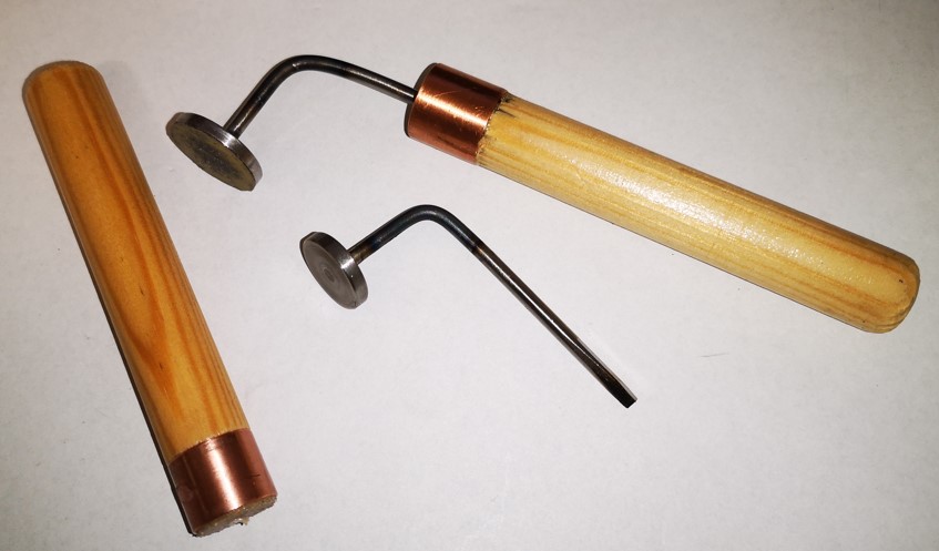
The blanks (no more than 12mm diameter) are made from a disc of 3mm ground flat stock  brazed onto a 3mm silver steel shaft.  Once brazing is complete the disc is trued in the lathe by gripping the shaft.   The shaft is then heated to allow bending at right angles and then mounted in a home made handle.   

The handle is around 75mm long and is made from 15mm wooden dowel with a strengthening collar made from a 15mm length of 15mm copper water pipe.  The dowel is turned down such that the collar is a push fit and a 3mm pilot hole is drilled in the end face.   After preparation the dowel is varnished with the collar in place.  These homemade handles get used on other tools around my workshop such as needle files and gravers.

I agree the wet and dry will not last for ever but it is a cost effective and flexible option to a box full of ‘proper but not used very often’ Bull’s Foot files.  An alternative to using wet and dry is to Araldite shaped pieces of broken files onto a similar shaft and handle concept.  These would last longer but once again more handles would be needed to cover the grades of file needed.  The spacer medium would still be required to protect the plate surface.

For those of you more adventurous there is an alternative handheld solution detailed on the Sherline website.

Similar or related subjects : –

Adding thrust bearings to the Myford Super 7 with Clough42 ELS fitted

Some time ago I documented my implementation of the Clough42 Electronic Leadscrew on my Myford Super 7 Big Bore lathe.   I also wrote up adding thrust bearings to the top slide and cross slide adjusters.   What remained outstanding was adding thrust bearings to the leadscrew.  While there is a commercial kit from Hemmingway Kits to install these, my implementation of the ELS involved a direct drive to the leadscrew at the tailstock end of the bed and made things difficult – I ran out of length on the leadscrew.

After considering the situation I opted to retain my ELS drive concept and gain space for the bearings by shaving metal from the Myford leadscrew bracket.  It is not an ideal modification as I am always very reticent about physically changing the structure of my machines.   Despite this I have to say it seems to have paid off and I now have a very stable and repeatable leadscrew feed from the ELS.  Here is a photo of the result.

modification to the leadscrew mounting for adding thrust bearings
The final assembly using the ELS drive concept to the end of the leadscrew and how space was made for thrust bearings to be fitted

I have added details of the modification to the original thrust bearing write up and this can be downloaded as a PDF from the link below.

Myford Super 7 Thrust Bearing Mods including leadscrew

Similar or related subjects : –

Rear Parting Tool Post on Myford Super 7

 I’ve been meaning for some time to make a rear tool post for my Myford Super 7 when parting off material.   There are various comments on the web about how a rear mounted blade is the best way to succeed for this activity.

Hemmingway Kits here in the UK offer a kit of materials and instructions based on the Geo. H Thomas design as detailed in his ‘Red Book’  (ISBN 1-85761-000-8).  This seemed like a good route to take.

The kit arrived with all the materials and documentation needed including a casting for the body of the post.  You do have to make a couple of cutting tools as part of the activity but again the material is supplied for this.  I found that having access to the Red Book in conjunction with the Hemmingway kit notes helped me better understand what was involved.

Having the Tormach CNC mill allowed me to depart slightly from the intended construction  but it all came together very well.   I had some Myford Aqua blue paint to hand from my Clough42 Electronic Leadscrew control panel enclosure and this finished off the project nicely as shown below.   However I do need to crop back the excess on the rear of the blades before blood is spilt.

Hemmingway rear tool post parting tool holder
The finished rear parting tool holder made from the Hemmingway Kit

Trial cuts have so far been excellent. I can now use the power cross feed when parting brass which is a major departure.  Overall a good addition to my workshop assets and a relaxing pleasure to make.

Similar or related subjects : –

Myford Super 7 backlash solution with thrust bearings

One Job Leads to Another

I had a job for a customer that needed two M18 screws cut on the ends of a  shaft.   I have never cut anything that size before but fortunately I have installed the Clough42 Automatic Leadscrew system fitted to my Myford Super 7 Big Bore lathe.

I tried some trial cuts using the Geo Thomas ‘Red Book’ top slide method but I found there was so much backlash on both the top slide and cross slide that I was struggling for consistency.   In the end I did a hybrid cut ‘nearly there’ using the ALS using plunge cuts and then I finished with a nut die that was happy to start on the part cut thread .   This gave me a clean finish to the thread and I was relieved to get the job done.   Note that my S7 is a ‘metric’ version but the leadscrew is Imperial so screw cutting using the ALS entails keeping the half nut engaged and reversing the drive.

With the job completed my thoughts came round to giving the Super 7 some TLC to try to improve the backlash issues.   I found various discussion threads about fitting thrust bearings to the cross slide and top slide but all referred to EBay thrust bearings that were no longer listed.   After some investigation I found Simply Bearings had two suitable items in stock.   The NTA916-TRA916 is a 9/16″ core diameter bearing and washers suitable for the cross slide and the NTA815-TRA815 is a 1/2″ set for the top slide.  I ordered two of each set.

The attached PDF link below gives details of how I implemented this modification.

Myford Super 7 Thrust Bearing Mods

Similar or related subjects : –

Adapter plate for a Tormach microARC to mount a Xin Dian centralising vice

I’ve made mention in another post of the arrival of the Tormach microARC to use on my Tormach PCNC440 CNC milling machine.   The microARC provides a 4th axis facility.

To date I have used this with the supplied chuck but there have been a couple of instances where a vice style stock mounting would have been useful.  I am indebted to David Loomes for bringing the Xin Dian centralising vice to my attention. 

Xin Dian centralising machine vice
The Xin Dian centralising machine vice

This is available from various sources on the Internet and at a delivered price of less than GBP100.   It is a lovely little vice.   It is supplied with an industry standard backing plate which is held in place with four M6 cap head screws.  The supplied backing plate is not suitable for mounting on the microARC .

A 3D model of the microARC is available as a Fusion file and this with some careful measurement allowed me to model a mounting plate for the Xin Dian to fit onto the microARC face.

As a secondary activity I edited the Fusion file to provide a simple sub-mounting plate for the Xin Dian vice on my PCNC440 tooling plate.

Details of both these mounting plates are contained in the PDF link below.

xin dian vice mounting plates

Similar or related subjects : –

Verified by ExactMetrics