Two variations on a theme
I recently had to turn a number of items on my lathe and wanted them to be consistent in length. These were long items, too long to reference with my home made Morse Taper depth stop.
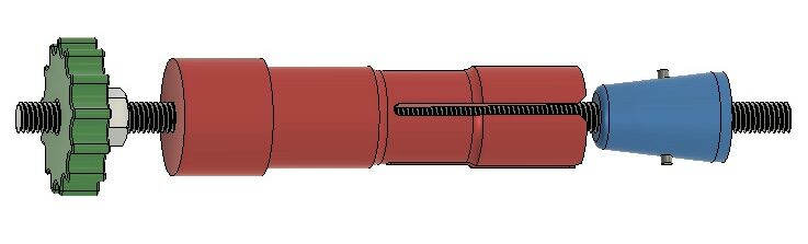
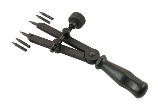
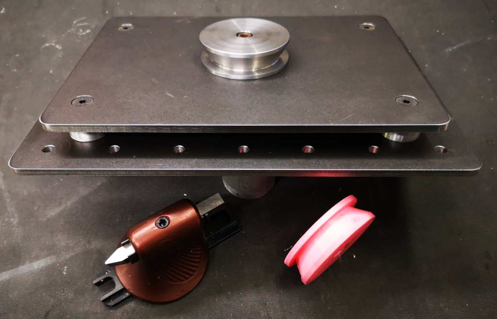
In desperation I raided my Sherline CNC Rotary Table hardware kit for my coaxial tailstock clamp. This is based on the Myford tailstock winding handle but without the handle. It clamps the lathe bore to the CNC table for cutting items needing indexing such as clock wheels. Wheel cutting is quite a demanding application. There is no tolerance for slippage or you will get to the last tooth and have only half half the material that you expected left to cut … and the box of shame looms.
The clamp is quite simple – the main body is an expanding collet, this mates with an expansion cone and a centre threaded rod. The cone angle is 5 degrees. There is a knob to tighten the assembly and squeeze the cone into the body to expand its arms. The body has four slots that two pins on the cone engage with to stop rotation.
Having finished the particular job in hand I put away the Sherline clamp and thought it would be useful to make a second version of the clamping collet dedicated as a lathe depth stop. I was rummaging in my metal stock for material to make this when the light bulb came on …. why not 3D print it? When the clamp is used as a depth stop there is no rotational stress. It just acts as a stationary reference stop that sits down the lathe bore.
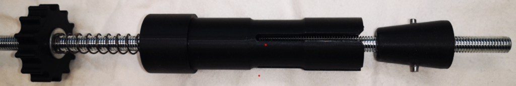
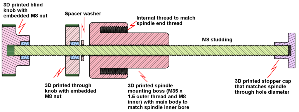
I copied the dimensions from the Sherline version and input this into Fusion. I printed the body, the cone and a knob (with an M8 embedded nut). The centre rod is M8 studding which passes through the collet body and then screws into the cone and then protrudes onwards to set the depth in the lathe bore. You would think that there needs to be a nut to lock the studding to the cone but the cone cannot rotate as it has the two locating pins. Providing the studding is stopped from rotation while the knob is tightened, the depth should be set solidly. A lathe depth stock is rarely an accurate setting tool but just a repeatable reference. The accuracy of the final cut is catered for by the tool position set and the various lathe DROs.
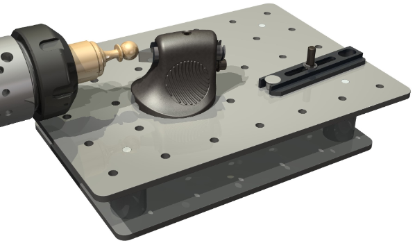
Printing this was a lot easier than cutting it from metal. No messing setting cutting angles etc. Here is the Fusion pictorial view and cross section.
After using it a couple of times I ended up putting a spring and two M8 washers between the body and the knob to maintain a slight pressure on the cone. The spring keeps the locating pins engaged in the slots on the body as the assembly is pushed in place down the spindle bore.
I also added a ‘top hat’ on the end of the M8 rod (not shown above) to give a larger surface area for the work piece to bear against. This would also stop wobble of the threaded rod as the spindle rotates.
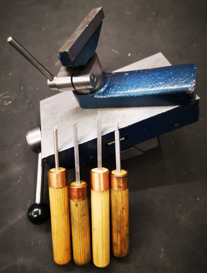
Attached below is a ZIP file with the body, cone, top hat and knob STL files. You will need some M8 studding, an M8 nut and some short M3 stubs for the anti rotation pins in the cone. If you add the spring then two M8 washers will be needed. All the threads are modelled in the STL files but will need cleaning up post printing. I printed in PLA+ and had the prints set to four perimeters. I superglued the two M3 studs in place. The tops of the studs should not protrude beyond the unexpanded body surface otherwise they will bind on the inside surface of the spindle bore.
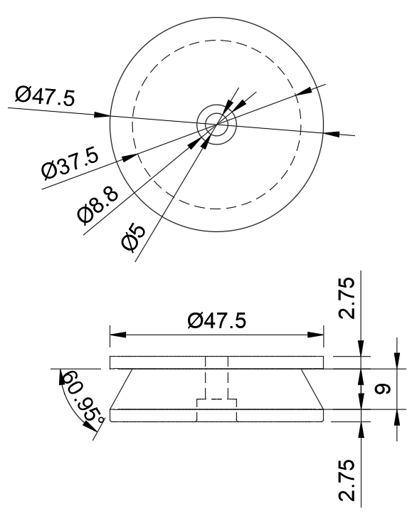
Things now went a little bit off piste …. I had forgotten that the end of the lathe spindle has a threaded section that mounts the bearing pressure collar. The exposed thread is normally protected with a plain collar. The thread is M35 x 1.5, something very easy to model and print via Fusion 360. Below is the relevant exposed thread with the protector collar removed.
Another light bulb came on (getting to be competition to Blackpool you might think). Why not make things very much simpler?
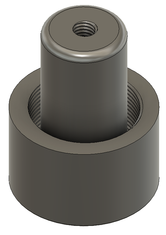
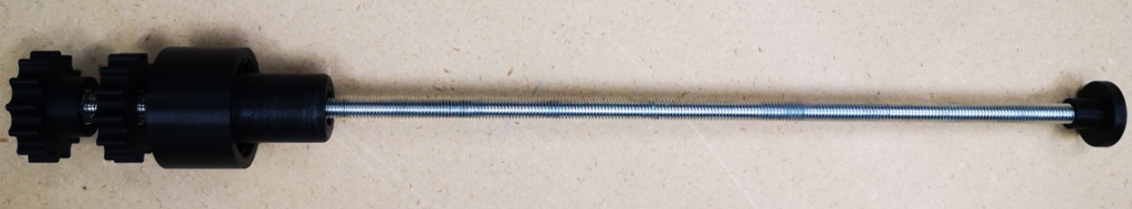
I modelled a boss to screw onto the M35 x 1.5 thread with a central core to fit down the spindle bore (26mm) and with a central M8 tapped hole. I also printed another through hole M8 knob, a M8 top hat and a new blind M8 knob. I now had a much more simple depth stop.
Here is the Fusion image of the boss. This would have been tricky to cut as one piece in metal but very simple as a 3D print.
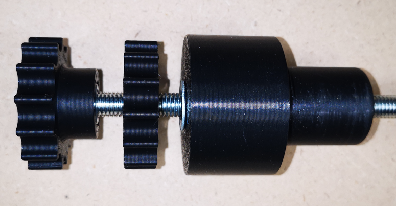
Here is a close up view of the final assembly with the top hat out of shot at the far end of the M8 studding but shown in the second image. The knob on the left grips the end of the studding to allow easy adjustment of the position of the top hat. The inner knob locks the studding in place against the boss. Both knobs have embedded M8 nuts glued in place. (Note the bend on studding is a photographic distortion).
Two solutions for a depth stop. The second option is peculiar to the Myford and the first solution more universally adaptable to other lathes. The following download ZIP file contains the STL files for both versions and there is a second ZIP which has the Fusion 360 model for those wanting to tweak. Either version will make a useful addition to the workshop tooling.
Update : I had comments from some readers that the internal thread on the boss was very tight mating on the spindle thread. Being 3D printed it will depend on the slicer and the 3D printer for its fit. I have tweaked the Fusion 360 model to be more tolerant of this and new STL file is on the link below. See the later post on how to do this.
Links to similar or related post are listed below : –