

I am now running Version 21 of Gearwheel Designer and it gets better all the time.
I decided to make a ratchet wheel as my next test. This highlighted the need to think about the process order on the mill. Below is the design image in Gearwheel Designer.

My CNC sequence was as follows : –
- Cut the square brass blank a little oversize and draw a diagonals on it to show the nominal centre (Manual operation).
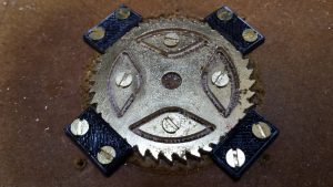
- Drill four holes in the corners outside of the working area of the cutting and use these holes to fasten down the blank to the milling table (which I had protected with a piece of MDF). (Manual operation)
- With a drill bit as appropriate, drill radial holes in the centre of the spoke petals and also the centre hole.
- Fasten the petals down to the MDF using these radial holes.
- Cut the gash outline of the wheel.
- Remove the four corner screws and remove the liberated brass outside the gash cut.
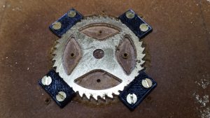
- Cut the rough pass on the teeth.
- Cut the fine cut on the teeth.
- Fasten down the periphery of the wheel with small clamps.
- Gash cut the spokes to leave the petals free from the blank.
- Remove the screws holding the petals and remove the brass liberated.
- Run the final cut on the spokes.
- Job done apart from a light sanding to remove any small burrs.
Some more images follow : –
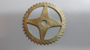
The purists will now tell me how it isn’t a proper wheel because the crossing interfaces to the rim have radius rather than a sharp corner.
Well a file will soon fix that …. and I can tell them how I watched another three episodes of House of Cards while this wheel was being cut.
Similar or related subjects : –
- Arduino Processor Reference Clock Accuracy
- 3D Printed Length Gauge for In Barrel Mainsprings
- The “Modern Clock” by Goodrich
- Parting Off on the Lathe
- Workshop storage update using Spacemaster 5L boxes
- Microset Timer interface using Fusion 360 3D model with Fusion Electrical
- Clock adjuster rod for measuring spring and fusee drive power
- Plastic heat sealer – a useful workshop asset
- How to square up a scrap piece of stock ready for machining
- Deburring techniques in the home workshop