

I just dared to hit run on my first attempt at Mill Turning. I need to qualify this in that the first run I was cutting air above the set up. It looked OK so I put the real material in the spindle and I got a turned part as designed in Fusion 360. I didn’t part it off and you can see the result below.
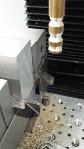
Mill Turning is where you place the material you want to shape (usually a rod of some kind) in the mill spindle instead of a milling tool. The tools are mounted on the milling table (see above in the vice) and are completely stationary but move via the actions of the table in the X axis and the spindle in Z. The software is conned into thinking the material is really a milling tool and that the tools are the material.
It has taken me the best part of a week to work out how to model this in Fusion 360 and I have been helped enormously by watching Jason Hughes on YouTube. It involves allocating a different Work Coordinate for the location of each tool.
If I can get this more streamlined and get some better lathe tooling in place to support it, then I will be able to turn clock pillars. This was the last stumbling block in moving to CNC assisted clockmaking.
Tonight I am a very happy bunny. A glass or two of Merlot with dinner perhaps ?
Similar or related subjects : –
- Arduino Processor Reference Clock Accuracy
- 3D Printed Length Gauge for In Barrel Mainsprings
- The “Modern Clock” by Goodrich
- Notepad ++ for GCode Editing
- Parting Off on the Lathe
- Local power USB switching circuit
- Tormach PCNC440 X Axis limit switch repair
- Workshop storage update using Spacemaster 5L boxes
- Microset Timer interface using Fusion 360 3D model with Fusion Electrical
- Clock adjuster rod for measuring spring and fusee drive power