Fusion Tips using 3D Connexions SpaceMouse

You can buy the 3DConnexion SpaceMouse and CADMouse combination as a single package.   If you haven’t got a SpaceMouse you are missing a major enhancement to your pleasure while using Fusion.  It’s worth every single penny.

The SpaceMouse is a 3D manipulation mouse and the CADMouse is just a conventional mouse.   Originally when bought as a package they shared a common dongle.  I found that servicing the two devices simultaneously via one dongle led to a laggy experience.   The new versions are Bluetooth connected and are not affected in this respect. If you are considering getting one (and you should) then keep an eye on EBay.

There are two programmable buttons on the basic SpaceMouse which can be preset to shortcut functions.  I have my left hand button set to ‘ISO-1 view’ which means I can quickly reset the modelled object on screen to its home view.  You know how it is when you get totally disorientated when spinning and zooming …. Note that there are more complex versions of SpaceMouse with loads of buttons but this would be asking too much of my memory.

To set up the buttons you need to be in the Fusion Design screen.  The 3DConnexion software ‘knows’ what application you are using and which module in the application so this is important.  In a wider sense this allows the SpaceMouse to be customised specifically to every application you are using on your machine.  (Google Earth fly-by is fun with the SpaceMouse).   

To access the settings menu, click on the right hand end of the Windows taskbar and then right click on the 3DConnexions logo to open the Settings menu.   This will bring up the following menu stack. Note that you must have the Autodesk Fusion – Design… as the title.   The available button options are specfici to each of the other Fusion modules. For example I have two other functions set for when I am in the Electronics PCB design module.

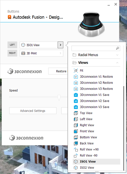
If I right click the SpaceMouse button this takes me to the 3D print submenu in Fusion.   This is the same as clicking on the File menu in Fusion and clicking 3D Print.   This will bring up the following 3D print sub-menu.

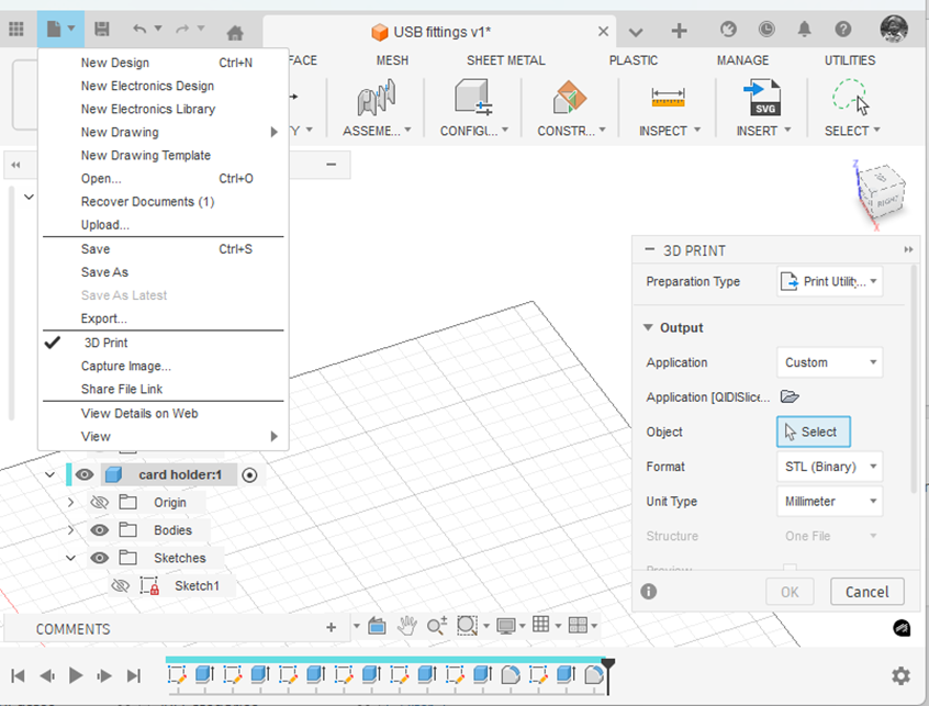
(Side comment – if you haven’t discovered it yet … the ‘House/Home’ icon shown at the end of the top menu takes you to a wonderful full page view of all your recent modelling activity. Yes I know it has probably been there ages. I always was a slow developer but what joy when I found it).

Note that I have the Application box set to ‘Custom’ and the Application folder below this is pointing to the QIDI Slicer EXE file which is found in Explorer as below.  Note this is in ‘Program Files’ and not ‘Program Files (x86)’.

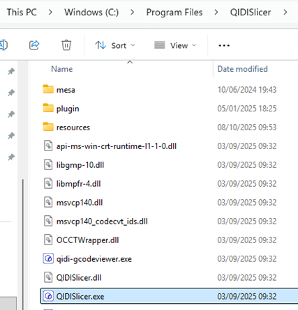
Click on the little folder icon in the sub-menu and navigate to and highlight the .EXE file location.  You will now have a direct boot to the slicer software you are using.  This will be activated either from the File menu or your SpaceMouse programmed button.

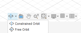
One extra comment – remember to set the Free Orbit setting or the Spacemouse will resist certain orientations.

Have fun !

Links to similar or related post are listed below : –

Tap shank adapter for 4mm AF hex drivers

I usually 3D print all threaded holes as a modelled thread rather than tapping drill size hole which would need full post print tapping. As the intended thread size of modelled threads reduces so the print quality of the thread can be a problem. This usually leads to a quick post print run through the thread with a manual tap.

Thread quality and strength can be improved by increasing the number of perimeter prints via the slicer software. This makes the printer add extra print lines around all external surfaces before it does the infill. This is even more important if you are going to use brass inserts for your threaded mountings as it gives the insert more plastic to melt into.

The problem with post print clean up tapping is getting the tap to start perpendicular to the already printed tapped hole. If the hole is small (say M2) the size and mass of the tap holder adds to the wobble difficulty of getting it ‘plumb’.

In the past I would mount the tap in a small toolmakers chuck as this gave an extended length to the tap for the eye to judge the ‘plumbness’. I didn’t have enough chucks with the right size collet to cover all tap shanks.

Some time ago Clough42 recommended a small electric screwdriver that had 4mm AF inserts. I found this one on Amazon. There are also many other electrical and manual screwdrivers that use the 4mm AF insert standard.

It struck me that if I could make a set of adapters to mount in the screwdriver chuck to hold the tap shank this would ease the post print tapping problem. The length of this particular screwdriver body gave a better ‘to the eye’ perpendicular check. The added ability to electrically drive the tap meant that the perpendicular setting was more easily maintained. The speed and torque of the driver would also act as a break clutch.

I debated a lathe activity but then thought why not a 3D print? I created a model in Fusion with Parametric functions for the tap AF dimension and square driving section length.

Not all taps are created equal so these two parameters can be easily adjusted using the parametric function to match your tap sizes. Print time was around 9 minutes on my Qidi X Smart. I printed the adapters in PLA+ vertically off the bed as shown and in 0.2mm layer height. I set the slicer for 6 perimeters on the print, a 6mm wide outer brim for build stability and auto support off the build plate.

The adapter boss section will accomodate up to M5 size tap shank dimensions (3.9mm AF, 8mm length). Any size greater than M5 will usually print very clean and not need post print fettling.

Here is the Fusion file for those interested.

Links to similar or related post are listed below : –

Custom Threads in Fusion

The Christmas period tends to be a lazy period to sit and wander round the web in front of the log burner instead of getting grubby in the workshop. This is greatly assisted with a glass of something and a large slice of Christmas cake accompanied by a similarly large slice of Wensleydale cheese. (It’s a Yorkshire thing. Try the combination. You might get hooked).

In the course of one of these surfing indulgencies I came across a custom thread creator for Fusion. I am indebted to Matt Beech for this creation. See his GitHub page here.

https://matthewmcneill.github.io/FusionThreadsGenerator/

He has already created XML files for BSW, BSF, ME, BSB profiles. You simply copy the XMLs into the Fusion folder on your machine. This will be found on your machine in the following path : –

C:\Users\*your user name*\Autodesk\webdeploy\Production\<version ID>\Fusion\Server\Fusion\Configuration\ThreadData

Matt’s GitHub page also mentioned ThreadKeeper which is a handy Fusion plugin that protects your custom XML files as they sometimes get deleted when Fusion updates. This little app can be installed from the Fusion App Store and will appear on the Utilities tab in Fusion.

https://apps.autodesk.com/FUSION/en/Detail/Index?id=1725038115223093226&appLang=en&os=Win64

You need to preserve your custom XML files in the ThreadKeeper folder.

Hope that helps someone. Now back to the woodburner, cake and cheese.

Links to similar or related post are listed below : –

Upgrading to Windows 11

After a great deal of thought I bit the bullet and have migrated to Windows 11. This has come about simply because Autodesk will not be supporting any issues with Fusion while running in Win10 and the spec of the machine being used is more critical.

I hate doing an ‘upgrade’ onto an existing machine where you are never clear what baggage is already there and what its impact might be. My existing machine was not hardware compatible and so instead I went for a clean new machine. After some searching I opted for the Geekom GT2 mini PC which has a decent spec and lots of USB ports.

https://www.geekom.co.uk/geekom-gt2-mega-mini-pc

Note the GT2 has embedded Intel graphics rather than a conventional video card that you would fit to a standard PC. How much this impacts I will have to see although Fusion seems to load and work faster and is more responsive using my 3DConnexion Spacemouse.

The pain of a completely new machine is transferring all your old loved apps and trying to remember where the ISOs are and the associated licence codes. I am not the most disciplined in this respect. There is however a panacea to this in the form of LapLinks PCMover Pro. You simply connect the new and old machine together on the same network and leave them in peace for an hour or so and hey presto all your stuff gets transferred. It is not 100% perfect but it does save a lot of frustration and heartache.

Another issue with Win11 is the pressure to use Office 365 which does not appeal. I prefer the old school Windows Office and you can get the 2021 version quite cheaply on EBay.

The final concern with Win11 is all the baggage you get with it that you don’t want/need. There is a nice little app that solves this called quite appropriately CrapFixer. This is well worth checking out.

So most of the upgrade has gone to plan and has been less stressful than expected. There are still one or two apps that are not loading but I’m working on them.

Time will tell ….

Links to similar or related post are listed below : –

Model Railway Track Testing Monitor

My local Model Engineering Society is very conscientious regarding the maintenance of the club running tracks. We have both ground level (7.25″) and a combined raised track for 2.5″, 3.5″ and 5″ gauge running.

The Society has decided to upgrade the support structure on the raised level track. The old wooden beams will be replaced with new plastic decking board based structures.

The upgrade is for the full length of the track (1361ft/ 415m) and will be a major over winter activity. Once the rails have been re-fitted to the new supports there will be a need to make sure the track bed is correctly aligned to match the geometry of the new support structure and the route curvature and banking.

Some while ago DroneBot posted a video about using an Inertial Measurement Unit (IMU) with an Arduino to create an electronic spirit level. This struck me as being a potentially useful device that could be enhanced for measuring track characteristics. My idea was to check the existing 5″ track profile so we had a reference before the upgrade. Once the upgrade is completed, the same measurement run could be made to help to speed up alignment.

A prototype unit was based around an Arduino Uno. The Arduino code has edits to provide additional LED ‘bar graphs’ and a sensitivity adjustment. The circuitry was accommodated on a bespoke hardwired Shield connected to the IMU. The prototype unit appeared to work very well so a more engineered version followed with a 3D printed enclosure and professional PCB both of which were designed in Fusion.

Mission creep alert …. I decided to add a GPS facility so the readings around the track could be logged. I added an OLED display and also a memory card facility to record the results for future reference. The code runs on a Seeed Xiao. The GPS unit was housed in a separate 3D printed enclosure and connected via a three wire interface cable. A 3D printed battery holder for a 12V battery completed the installation. The GPS unit takes the slope and tilt information and adds this to the displayed data. Here are Fusion graphics of the LED shield that plugs into the UNO and the GPS receiver and display.

A surplus to requirements bogie was found in the club carriage shop. This had significant mass to make a stable measurement platform. The tilt meter, GPS unit and battery pack were mounted onto the bogie and for further visual cross checking a bubble level gauge was included. Here are some images (wet images …)

Here is the GPS unit OLED readout

A couple of runs (actually very slow walks) were made around the track. The logged results were very impressive and highlighted one or two suspect cambers on the track. Using an App called GPS Visualizer it was possible to take the logged results and superimpose them as a snail trail on Google Earth. Visualiser also colour grades the results to provide a more obvious display of the track variations.

This has been an interesting and useful project. It might be of use to other clubs needing to check track characteristics. I have ordered a batch of PCBs for the LED display Shield and for the GPS logger from PCBWay. Let me know if these boards and the associated Arduino code are of interest.

Links to similar or related post are listed below : –

Verified by ExactMetrics