How I Create Robust 3D Printed Knobs
First of all an apology … colour has arrived as I have finally migrated to the WordPress Guttenberg editor from the Classic Editor. The Classic is due to be phased out in the near future so I thought I had better jump before I was pushed. I can see the advantages this offers but I am still getting to understand the different way of working.
That aside, onto the post …
The problem with creating 3D knobs is that they can lack robustness unless they are made less dependent on the printed material. There are various ways round this but the easiest method I have found is to embed a conventional metal thread or nut combination. This allows you to be as stylish as you want with the shape of the knob while knowing that the core locking material is resilient to twisting.
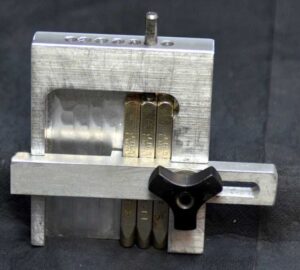
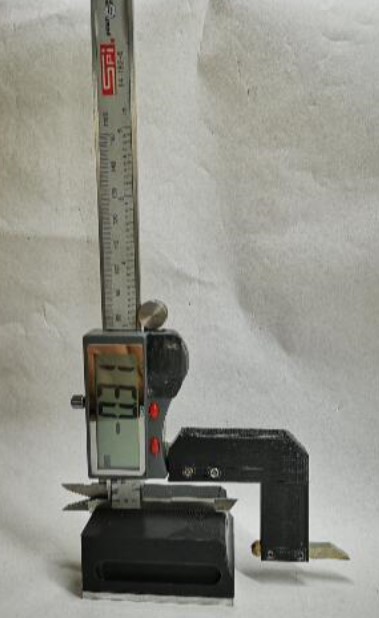
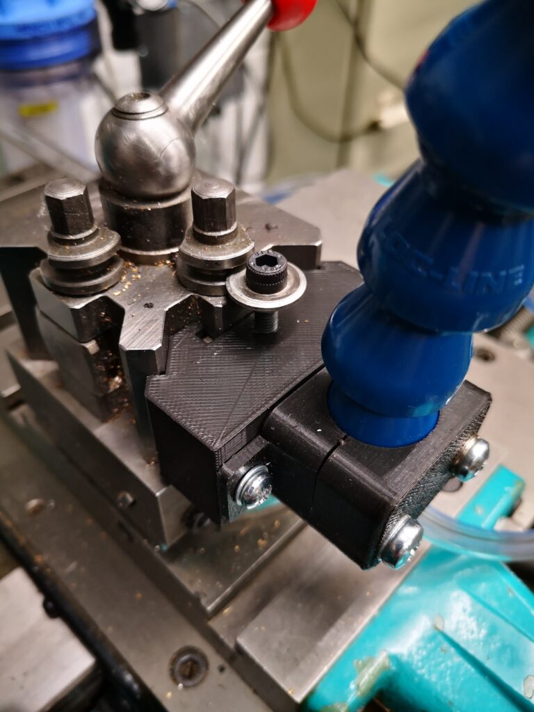
A couple of good examples that I have produced recently are a replacement knob for holding the cover of my BK3 bandsaw in place and one to allow hand tightening of a U bolt clamp to a pipe.
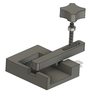
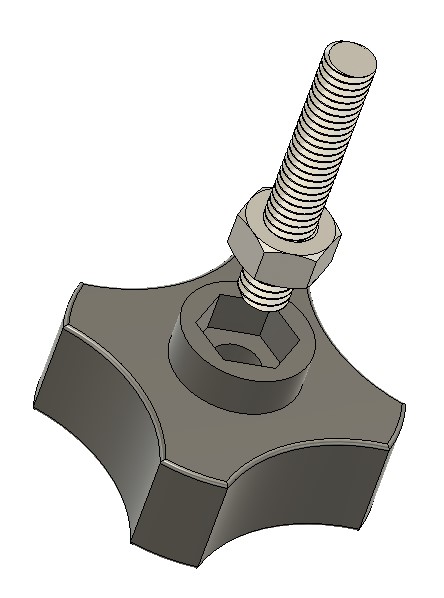
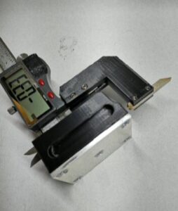
The BK3 clamp required a protruding thread (male) while the U bolt clamp needed a female style. Both were designed in Fusion 360 and embed either a nut or a thread and nut combination as the following images will show. The basic form of the knob is similar in that is has a cavity for the chosen nut size and for the female form may or may not have a through hole. The 3D printed body can be as fancy as you want to make it. I have been pleased with the basic shape shown below as it allows a firm grip to be applied.
Depending on how tight you can make the fit of the nut, the female form may need a dab of SuperGlue to hold the nut in place in the printed body and the male form will need Locktite on the thread and nut.
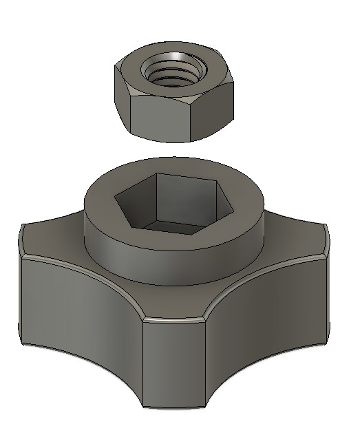
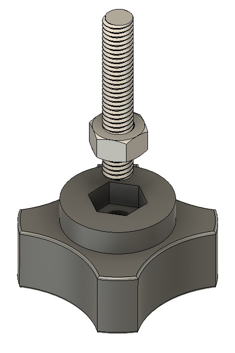
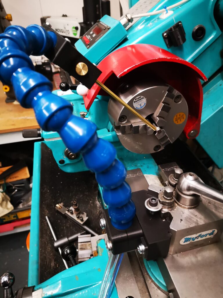
While both of the versions shown above have a boss for the nut cavity, this could equally be inset into the main body of the knob so it finishes flush. Next time you shorten a screw, save the thread offcut for future use on a knob.
Links to similar or related post are listed below : –
- Hybrid 3D brass threaded insert tool
- Tap shank adapter for 4mm AF hex drivers
- Qidi Slicer auto support error on my part
- Qidi X Smart 3 revised fan installation
- Qidi X Smart 3 tweaks
- Qidi X Smart 3 special weekend pricing
- Stop losing Qidi ifast 3D prints down the chamber front gap
- Fitting a Bento air filter to a Qidi ifast 3D printer
- 3D Printed Brass Threaded Insert Soldering Iron Stand
- eSUN filament reel silica drying pod