A handy reference for Fusion 360 parameter functions
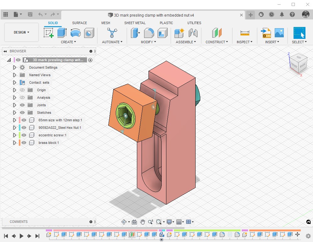
Fusion 360 has an incredibly useful facility whereby you can make a model dimensions fully flexible through not entering fixed dimensions but instead make them a calculation. The calculation will be dependent on other attributes of the model in conjunction with mathematical functions.
Clough42 quite often uses this facility in his designs and there are some good tutorials in the Autodesk resources.
I had two problems in a recent model. The first one was where I had a dimension that I wanted to convert into a plain value rather than being associated with mm. This would allow it to be used in an equation. The second problem was needing to round a calculation result down to the nearest whole number.
The answer to the first problem was simple and obvious – divide the value in units by one unit. So something 200mm long becomes just plain old 200 when divided by 1mm. I was a bit red faced on that one.
On the second problem I searched everywhere in the Autodesk forums and found people mentioning ‘floor’ ‘ceil’ and ’round’ but it took a lot of searching to find a tabulated reference for the workings of the Parameter functions.
Having found the lookup details on the Autodesk site I have transcribed this into Woody speak which you can download as a pdf below and I have also added it to my Workshop Spreadsheet and there is a link to the latest version also below.
Links to similar or related post are listed below : –
- Fusion 2026 Update Furor
- Confusion over the 10 files limit in Fusion hobby licence
- DXF import to Fusion
- Adding a second monitor to your Fusion work space
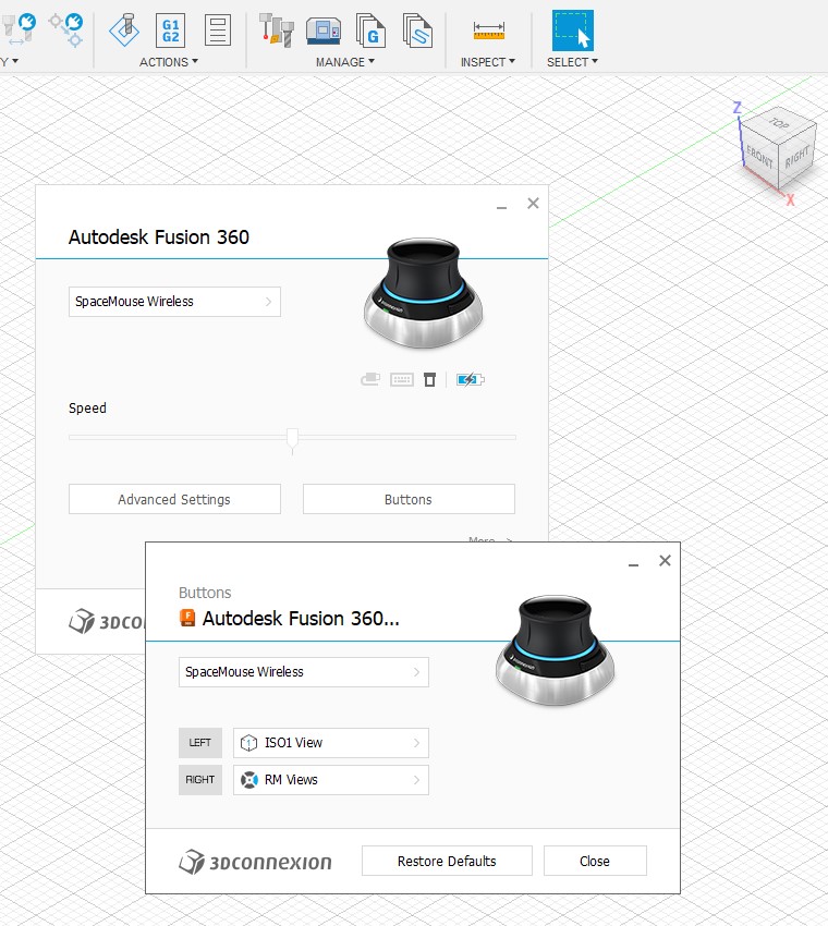
- Fusion Tips using 3D Connexions SpaceMouse
- Custom Threads in Fusion
- Upgrading to Windows 11
- Fusion Electronics Library Notes and Crib Sheet
- I had a ChatGPT experience
- Fusion Sheet Metal model export as PDF