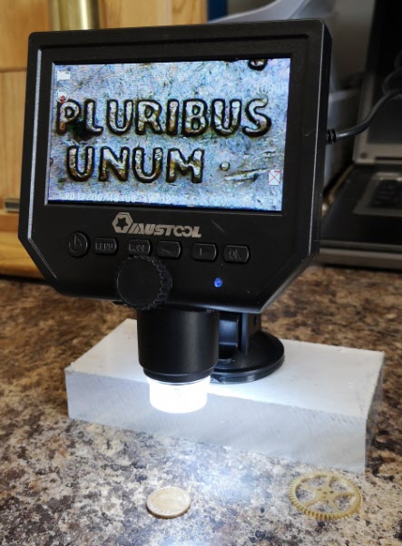
I often have a look on Banggood for tooling items for the workshop but the other day a low cost microscope caught my eye. I regularly get thin slivers of brass and steel in my hands and fingers and they are a real pain to find never mind remove. I thought for the price being asked this microscope might make a low risk purchase to help my failing eyesight.
It arrived today, looked really cheap and nasty out of the box yet I am staggered by what it does. The screen is HD and there is a card slot for local storage. You can record stills or video. Have a look at the following link : –
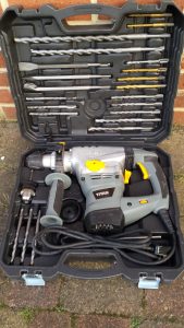
Some time ago I saw an advert offering a big discount on a SDS Rotary Hammer drill from a local tool store. I had no idea what a SDS drill was but one of my associates convinced me it was a good deal and worth getting. Looking like a weapon out of Star Wars, it has since sat under the bench in its carrying case and never used …. until today …..
SDS Rotary Hammer Drill
I had to fasten a new garden hose to the external wall through an outer cement facing and into brick. Normally if I can see the mortar between the bricks I cheat and fasten into the mortar. Today however I could not see what was behind the facing cement and the hammer setting on my normal hand drill was making no impression. Light bulb moment …. let’s try out that SDS.
The wall could have been made of cheese such was the speed that the holes were cut. Lovely machine. If you haven’t got one – get yourself a SDS !
When I put together the package of items that I would be ordering with the Tormach PCNC440 I probably made a mistake. I wanted a machine vice (vise if you over the Atlantic) and the recommended size for the 440 was a 4″. However a jaw set was not available with this size the same as it was with the 5″. After checking with Tormach I ordered the 5″ in the belief that it would be usable.
The 5″ is serious lump of metal and really only fits on the 440 table long ways on. The jaw set is really nice however. Sad to say that none of it has been used so far and if I am honest it is unlikely to be used. A large and heavy white elephant sits in the corner of the workshop. It is going to cost more to freight it back to swap out than is economic. Offers gratefully received !
What to do ? Looking around I found that Arc Eurotrade offer a range of machine vices. In particular I liked the look of the SG Iron Milling Vices as they have flexible jaw positions and had a ‘pull down’ action of the jaws on closing. They do not offer soft jaws but at a pinch these could be made as and when needed. I ordered a 100mm (4″) version and it is a nice piece of kit, seems solid, but not as heavy as the 5″ Tormach.
The vice did not come with any useful fixing clamps so what to do ? I had already made a tooling plate for the 440 table that has M8 holes on a 25mm matrix. The plate also has additional 4mm tooling pin holes within the XY limits of the spindle movement. The vice sits nicely between the M8 mounting holes and just needed some simple ‘L’ clamps to hold it down.
Designing and making the Clamps
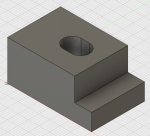
I designed something suitable on Fusion and did a 3D print of a prototype on the Sindoh 3DWOX to do a trial fit. This seemed to work fine so production of four metal ones was now needed.
Fusion 360 drawing of the clamping block
A debate now ensued. Options at this point were : –
Use the Fusion model to CNC/CAM repeat produce four individual clamps which would need three set ups to face and cut.
Use Fusion to extend the model to have four clamps in one piece of stock to be cut to length as needed but machined using a full CNC program of all four on one piece of stock. Each clamp would still need facing after cutting
Use the single clamp already drawn in Fusion and use WCS increments to hop along the stock and create four separate clamps for cutting off as needed. Still would need facing after cutting.
Finally given their simplicity there was the option to run them on the Myford manual mill ….
Outcome
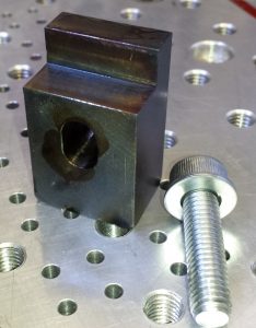
Well my hand goes up to say I funked it and made all four on the manual mill. I cut four pieces of stock (24mm x 19mm) to 40mm on the Kennedy hacksaw and faced the ends to length on the Myford mill. I jigged the Y position while sitting on parallels in the machine vice before cutting the clamping step on each. Next came an 8mm hole central in the slot before mill extending it out 2mm either side. Job done.
Would it have been faster on CNC ? I don’t really know. If I had drawn the ‘four in one bar’ version I think it would as there would have been only one setup apart from the facing off. If I had done the WCS based version of a single clamp then four set ups would have been needed, one for each WCS plus the facing. Either way both of CNC options would have increased my knowledge on CNC and I could have chalked another ‘result’ on the 440 fuselage mission tally board.
No excuses I know, but there is just something about manual milling and the intimacy of being in touch with the metal ……
The finished clamping blocks were made to suffer heat and then an oil dunking to blacken them off to make them look almost professional.
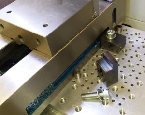
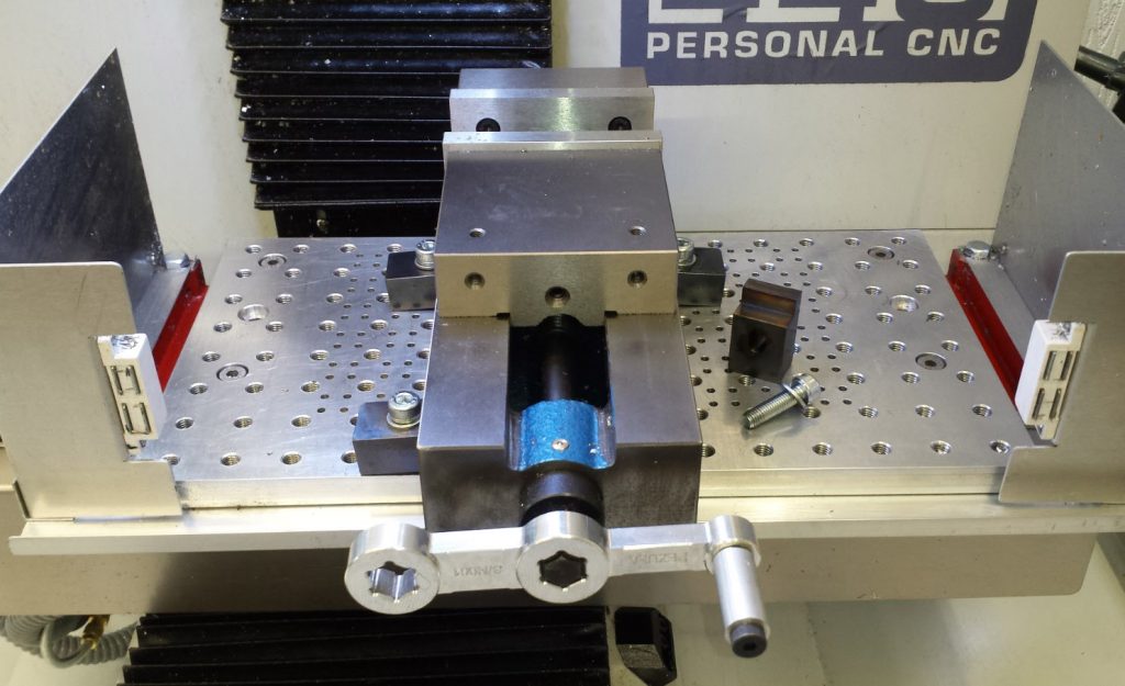
Vise Tooling ClampVise in place showing clamps and tooling pinsWide view of vise in place on 440 table. Note the NYC CNC training course handle finding a home.
So all of that was a bit of a ramble but you get the gist – CNC or manual.
Placement Tooling Pins
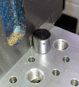
In closing the last thing I made was a couple of top hat tooling pins that sit in the tooling plate and align the vice position. This ensures the vice clamps can sit symmetrically either side of the vice. It makes for a quick set up if the vice has been off table. Note in the picture below the small piece of shim to get the alignment correct. (Lazy man syndrome creeping in again).
So the shop is now ready and better prepared to cut metal. Note also the NYC CNC training course produced vice handle being pressed into service on the new vice. Thanks to Kevin & John for that – was it nearly a year ago ???
Some days you walk into the workshop and while you know you have long term projects lurking, you just feel like having a distraction therapy day. For me this usually means adding some tooling in some way or other. Yesterday was one of those days.
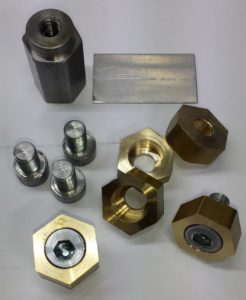
While looking around I spotted one of my storage boxes with all the parts I had accumulated to make some table tooling grip nuts as shown by Chris at Clickspring. These are similar to a commercial item. As I now have a tooling plate on the Tormach with a matrix of M8 holes it seemed like a good ‘all in one day’ project and would satisfy my therapy distraction.
Chris did not give any dimensions in his write up but there is more detail in his Patreon video which is subscription only. One gem he passed on was using a piece of 1mm thick material to offset the three jaw chuck to create an eccentricity to the locking nuts.
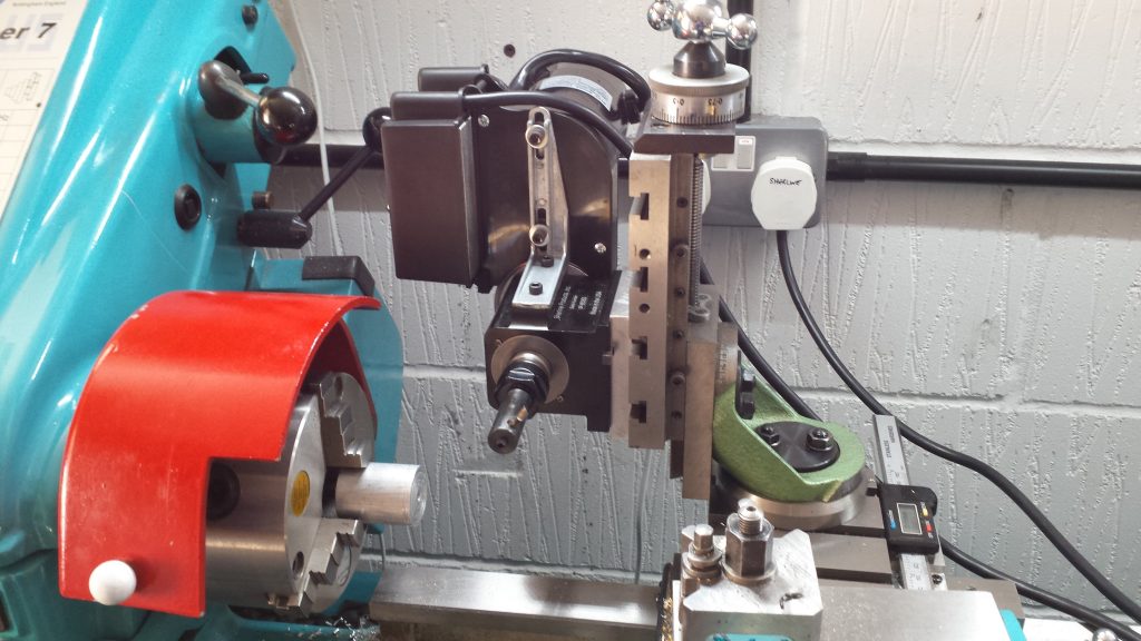
After completing the write up on the Sherline CNC Indexer for use on the Myford for clock wheel cutting, I realised that an important part of the process was the cutting mechanism itself.
I had adapted the Sherline headstock motor and spindle assembly to mount on the Myford vertical slide to act as a secondary cutting source. I use this for cutting clock teeth and for drilling holes ‘off centre’ to the lathe axis for such processes as arbor mounting holes.