My capacitor storage system was a mess and the arrival of some new stock kicked me into investigating a different approach to storage.
My initial thoughts were along the lines of buying one of the many pill storage systems offered online but they all seemed to be in garish colours and overprinted with days of the week etc.
In the course of further searching I came across this enclosed set on Amazon
For the price being charged (~GBP10) I was dubious about what the quality would be but on delivery I was pleasently surprised. The individual cases have a good action snap shut clasp on the lid and the outer container also closes and latches well.
I labelled up the individual cases using 6mm black on white tape using a Brother P Touch Cube printer (a lovely little machine).
While my initial need was for capacitor storage, I can see one or two more of these collections appearing in my workshop.
Links to similar or related post are listed below : –
Implications of milling tools and FlatCAM settings
I have spent many hours CNC milling circuit boards and I have documented my process elsewhere on this blog. The workflow is to first design the board in Fusion Electrical (or any similar CAD package) and export the manufacturing package as Gerber files for the copper artwork and an Excellon file for the drilling information. The manufacturing files can be imported into FlatCAM to convert them to CNC files for milling operations. This is all documented in my various ramblings. Double and single sided board are both accomodated by the FlatCAM software (you just need to get your head around manipulating the artworks).
I have been reasonably happy with the results that I achieve but as ever I tend not to rest with a process which has some niggles. As a result I keep searching for a breakthrough lightbulb moment or at least an interative advancement to make the results more repeatable/easier etc.
The first irritation was the cost of the milling tools I was using. I bought these in from Think and Tinker in the US and they cost around USD20 each for a 5 thou end mill. One careless twitch and your bank account takes a hit.
Let’s take a step back and refresh. The FlatCAM process produces a file that moves the cutter around a copper clad board to leave isolated representations of the copper trackwork. The gap between the wanted trackwork and the rest of the unwanted copper is defined by the width of the milling cutter. FlatCAM allows you to widen the isolating gap by taking additional milling paths side by side to each other with a defined overlap. With a 5 thou cutter I used to take two parallel cuts with a 10% overlap so the resulting gap was 9.5thou. This is a pretty narrow gap. The second time round cut does tend to raise burrs/slivers of copper and these can easily cause a bridge between the wanted and unwanted trackwork.
I make this more difficult for myself as I prefer to tin the copper after milling. (Scrub the copper clean, daub with flux and then deftly swish a soldering iron across the copper). The end result is good but the road to it is fraught. Before tinning, the board needs to be checked for milling shorts and all milling debris removed and scrubbed clean. After the tinning process there will be a number of self induced solder bridging shorts which also have to be cleared. A quick post tinning run round the board with SolderWick is a fast track route to remove these. The process works and the tinned end result looks much better than bare copper.
The first area of my current investigation was the milling tools. Could a larger diameter milling tool be sourced at a price advantage to the US parts and how much larger diameter would be practical to give acceptable artworks. The solution came from APT Tooling who are one of my regular suppliers of tooling. They provide a range of micro milling tools starting from 0.3mm (11.8 thou) and upwards. A single pass at this size would achieve the same isolating gap as the two passes with overlap with the 5 thou parts. Potentially a single path would reduce the swarf debris. APT offer two versions of the micromills with different hardnesses.
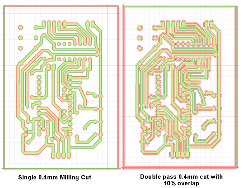
My PCB artworks are not high density and with my eyesight constraints I tend to stick with through hole components whenever possible and 40thou trackwork. I ordered in 0.3mm and 0.4mm milling bits (55 HRC versions) and ran the FlatCAM simulations of the 0.4mm isolation routing. The 0.4mm (15.7 thou) had the distinct advantage of creating a wider isolation gap while still allowing inter pin gaps to be cut. Adding a second cut with the same 10% overlap created a very acceptable artwork with a generous isolation gap. FlatCAM is nice in that providing the first pass can cut 100% of the isolation artwork, the second cut automatically truncates cutting gaps that would not be compatible with the artwork and damage the geometry. Here are some FlatCAM simulations
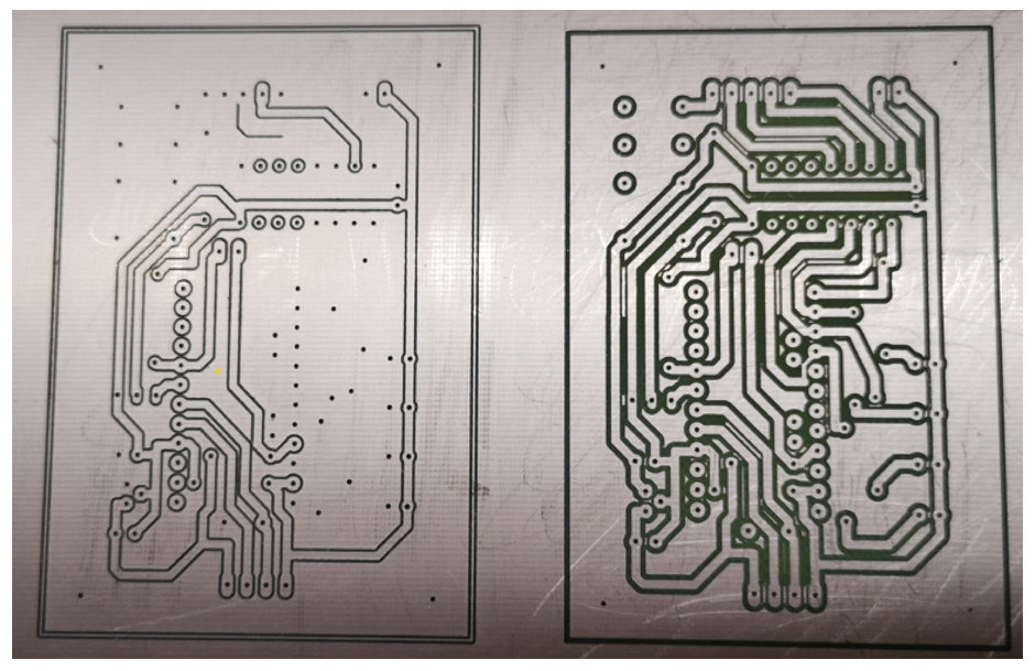
Here are the actual results of an artwork cut as a single 0.4mm cut and as a double cut with 10% overlap. (I terminated the single cut as the resulting partial artwork was enough to make a decision on). Notice that the double cut does leave mini floating islands between wanted trackwork as shown in the simulations. These can be easily removed with a hot soldering iron.
Whenever I get a new supply of PCB material I strip peel a small section and measure the thickness of the copper and the overall thickness of the board. Currently I am using RS single sided board (RS#219-2123) and this measures 2 thou copper and 60 thou overall. With this material I am running a 4 thou depth with a feed rate of 10″ per minute. I run all PCB operations on my Tormach PCNC440 with my home made vacuum plate.
Conclusion – for my level of artwork density I now believe I can get acceptable results using a 0.4mm cutter in either a single cut or overlapping double cut process. The APT 0.4mm tools are much lower cost than the US sourced parts and being larger diameter will hopefully be more robust. To date I have only tried their 55RHC versions. Note I always run both the milling cuts and drilling routines with spray coolant from a Fogbuster with my normal spray coolant (QualiChem Xtreme Cut 250C) . This has the advantage that the fluid enters the cuts and shows as a clear black line when the cut depth is correct or at least deep enough to go through the copper.
If anyone wants more information about my process, please get in touch.
Links to similar or related post are listed below : –
Some useful tweaks to the frequency standard and power supply
The FY6900 is a very versatile while relatively low-cost function generator. It has two independent signal sources each with a plethora of output waveforms and it also provides a frequency counter facility. The version I bought was specified to 60MHz and the cost was sub GBP100. It has a somewhat clunky user interface with a single-entry knob for settings but this can be supplemented with a USB PC graphical interface. While not the most sexy of instruments I have grown to appreciate it as a really useful cost effective addition to my electronics workshop.
While working on a clock related project, I had the feeling that the FY6900 displayed frequency did not necessarily accurately match other sources. As the unit does not have an input for an external frequency standard this made cross checking analysis difficult. Download the PDF below to read my notes on fitting an external reference input socket and also upgrading the 10MHz internal reference.
Of late I have been going round in circles on a project to keep our local church clock roughly on time. I say roughly as my idea of timekeeping does not accord with the aspirations of the village residents. Quote ‘ I only need to know when it is the time to go inside for a brew’ / ‘knock off for the day’ / ‘get my skates on or I will be late for work’ etc. I was thinking sub seconds and they were thinking a minute or so as being perfectly adequate. The exception is at 11am on the 11th of November when it has to be exact.
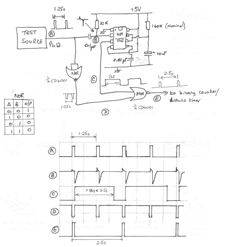
That as it may be, the project is moving along. The first problem was what to measure on the clock to reference the time adjustment. The pendulum (1.25s rate) is clearly the easiest choice and a sensor beam being broken by the pendulum swing will solve this problem. The slight problem is that the sensor will not necessarily ‘switch’ at the same time when being approached from the two directions of the pendulum swing. My Arduino skills might struggle to come up with some code to discriminate this so I reverted to simple CMOS logic. An ICM7555 acts as a monostable that has a period greater than one swing. This is triggered by the falling edge of the swing pulse derived from a simple differentiator network. The monostable extended period pulse is then gated with the incoming pulse using a CD4001 Quad NOR to always give me half the pulse rate regardless of the swing direction. That probably makes no sense at all so here is my back of an envelope waveform diagram and circuitry.
The circuit has turned out quite useful for other applications. I also refined it to have a CD4024 ripple counter fed from the output at E. This allowed extended logging periods to be achieved. I also utilised the unused gates on the CD4001 to provide an isolating buffer on the input signal. This meant the differentiating network would always see the same drive signal regardless of the incoming waveform and its source impedance.
Progress indeed. I now had a pulse train representing the clock beat period. All I had to do was measure the time taken between pulses and I could compare and adjust the pendulum rate.
Having got a reliable 2.5s pulse it was time to reverted to an Ardiuno UNO to measure the period. With some help from a friend we ran a sketch using millis to record the time between pulses. This minimalist sketch did not seem all that repeatable. I also did some tests with Frequency.h sketch code from the PJRC website (very useful source) and had similar poor results. I was using a FY6900 as my reference 1.25Hz signal and to get a 1.25Hz reading I had to offset the FY6900 quite a way from nominal. What to believe?
In a bid to get a known good reference I powered up my Arduino GTU-7 GPS module and measured the 1 second output pulse using both of the above sketches and the results were not much closer to the truth. I tried an Arduino MEGA instead of the UNO and got a different set of inaccurate results
This led me to think that the UNO and the MEGA must be the cause. Looking at these two boards, both have a 16MHz crystal which I (foolishly) believed was the processor reference and therefore could not be that much off frequency. Totally wrong. The crystal is for the USB interface, not the processor. Instead the processor has a basic 16MHz resonator – not a crystal. I got out the magnifying glass and discovered this piece of surface mounted wizardry. Low and behold if I put my finger on the resonator to warm it up, off it went into dodgy stability land. It was pretty awful. I could make my readings whatever I wanted them to be just by timing how long my finger was in contact with the surface mount resonator package. Chocolate fire guard indeed.
What to do ?
I downloaded the ATmega258P datasheet and found that I could replace the resonator with a crystal. This looked complicated with references to fusible links and reprogramming of the processor all of which made me twitch. The processor had been running on a wobbly 16MHz source so why not a less wobbly one?
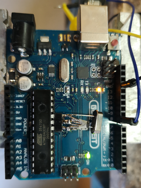
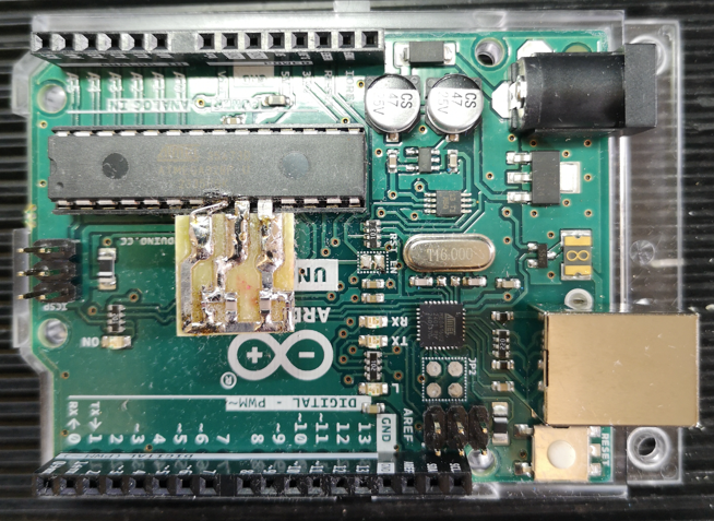
Rather than hack the UNO board, I eased the processor out of its socket and bent pins 8 (ground),9 (xtal) and 10 (xtal) out horizontally and plugged the processor back into its socket. Using a three pin socket pushed onto the pins as a mounting, I assembled the crystal across pins 9 and 10 and two shunt capacitors (approx 33pF) to the ground pin. The crystal came from RS Components (#8149440) and was a 30ppm spec. This socket mounted lash up was then pushed into place on the floating process legs – very healthy, no damage done to the processor or the board. Here is the ugly mess.
Switched on. It worked.
Suddenly all my test source readings took on a very stable repeatability and the readings were very close to what I expected. The GPS referenced 1s pulse was reading 0.999936 and my SY9600 was reading 0.999958. It looked like my new crystal reference must be slightly off frequency but a tweak of the shunt capacitor values will fix this. I think the SY9600 has a 10MHz TCXO so it should be good but I think I tend to believe the GPS pulse as being more accurately delivering a 1Hz rate.
The experts will tell me I should be adjusting the fusible links but I am inclined to stick with what I have got, it is working.
The result is I now have an ability to measure the pendulum rate and from this I can derive an advance and retard flag.
I am currently designing the front end circuitry as shown above into a PCB ‘shield’ to plug into the UNO. This will take the sensor input and give a slow or fast command pin output. More on this and general progress to follow.
Update (30/9/2024)
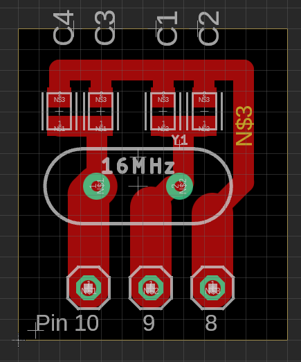
I changed the two crystal oscillator shunt capacitors to be a 22pFSMD in parallel with 1p8 caps when using the RS crystal as mentioned. Below is a suitable layout for the crystal and shunt caps. There are positions for two caps on each leg of the crystal. 15pF in parallel with 6.8pF would also work. I checked the frequency was close using a GPS derived 1pps signal feeding pin 8 on the UNO while running the frequency.h demo sketch.
The board can be connected using the mounting holes or it can be cropped and the residual pcb tracks used as direct connections using pins 10 and 9 both of which are bent out from the IC body. Pin 8 was left plugged into the IC socket and bridged and soldered across with a wire clipping to the crystal board. The crystal mounts on the rear. The board is so simple you could mill it on single sided copper clad with a burr in a Dremel.
The picture below shows the first milled version in place on the UNO. The layout above is a later tweaked version to better match the pcb pads to pins 9 and 10.
Links to similar or related post are listed below : –
I had received a clock to repair and wasn’t sure if the mainspring was correctly dimensioned. I remembered that William Smith had described a gauge for checking this in his book ‘Clockmaking & Modelmaking Tools and Techniques’ (pages 21 – 26). This gauging tool consists of two profiled plates that slide together to overlay the end view into the clock barrel. Bill’s design used 1/16″ brass plate but it struck me that a 3D printed version would be equally suitable and much quicker and easier to make.
In use the gauge is overlaid on the end view of the barrel as shown below. The point A is aligned with the outer diameter of the barrel arbor. The top plate is then slide until the inside edge of the barrel wall is aligned with point B. For a correctly chosen mainspring it should align with the corners C and D.
I sketched Bill’s design in Fusion 360 and extruded the two component parts to have a 2mm thickness before printing on my Qidi X Smart 3 in PLA. The two parts are fastened together to be a sliding fit with two M4 screws. The threads for these are modelled in the 3D print. A handling knob can be added in a similar fashion.
Here is my PLA printed equivalent.
The STL print files can be downloaded on the link below. It is not something that you will use every day but just a ‘useful to have when needed’ item. “Better to have it and not need it, than need it and not have it” (Jimmy Diresta).