I registered with Tormach for the free upgrade to the new release 2.x.x of PathPilot. A memory stick arrived this morning with the new code. It is fairly complex process but their documentation is quite easy to follow and understand.
All seems to have gone well with the upgrade except I can no longer see the shared drive for dropping files into nor can I get the Dropbox feature to load. All of which suggests the network connection is not working but I not winning so far. Gloom but not a disaster. Fresh eyes another day.
I am now running Version 21 of Gearwheel Designer and it gets better all the time.
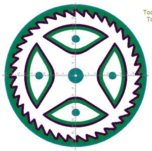
I decided to make a ratchet wheel as my next test. This highlighted the need to think about the process order on the mill. Below is the design image in Gearwheel Designer.
My CNC sequence was as follows : –
Cut the square brass blank a little oversize and draw a diagonals on it to show the nominal centre (Manual operation).
Drill four holes in the corners outside of the working area of the cutting and use these holes to fasten down the blank to the milling table (which I had protected with a piece of MDF). (Manual operation)
With a drill bit as appropriate, drill radial holes in the centre of the spoke petals and also the centre hole.
Fasten the petals down to the MDF using these radial holes.
Cut the gash outline of the wheel.
Remove the four corner screws and remove the liberated brass outside the gash cut.
Cut the rough pass on the teeth.
Cut the fine cut on the teeth.
Fasten down the periphery of the wheel with small clamps.
Gash cut the spokes to leave the petals free from the blank.
Remove the screws holding the petals and remove the brass liberated.
Run the final cut on the spokes.
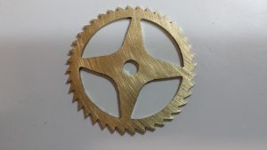
Job done apart from a light sanding to remove any small burrs.
Some more images follow : –
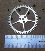
Gash cut done and teeth cut twice round. The clamps are in place holding it down while the petals are cut.Petals cut and removed for the final cut on the crossingsFinished wheel after a light papering
The purists will now tell me how it isn’t a proper wheel because the crossing interfaces to the rim have radius rather than a sharp corner.
Well a file will soon fix that …. and I can tell them how I watched another three episodes of House of Cards while this wheel was being cut.
I came upon the Delph site and was excited at the possibility to cut clock wheels on the Tormach PCNC440 as this was one of my prime motivations for the purchase. Does anyone love crossing out wheels ?
Delph has been feeding me with updates to their code and it is starting to make sense what it is doing and I like it. Today I have run a wheel on slightly hybrid code (Delph plus my direct G Code hacks) and I am impressed so far.
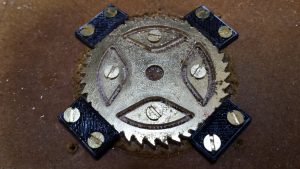
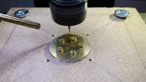
The Delph code lets you design all manner of wheels for clock and other applications. You can define the style of the teeth, the crossings etc and you can drill or mill arrays of holes. You can also define the order of the machining processes. I bolted down a square of brass with corner holes holding it down – you can see the holes in the MDF below. Next I had the Tormach PCNC440 drill the three sets of holes in the blank, then cut the blank to circular size to match the teeth maximum diameter. In the picture the mill is cutting a rough cut first pass on the teeth using a 0.7mm carbide cutter. Next is the tooth fine second cut and then I can cut out the crossings which is what the five screws are for – holding down the petals that will become free once profiled.
First wheel tooth being cut using the Delphe application.
Update : –
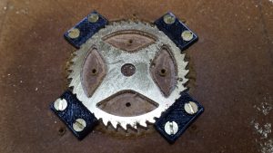
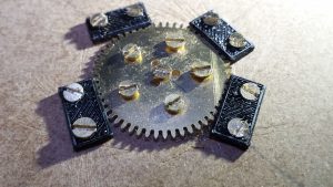
All went well in the first rough pass on the teeth called a Gash Cut in the software. I was running at 4000 RPM and 5mm per minute and each tooth was taking 4 minutes with a slow 3mm lead in. The second finishing pass was much quicker and now only leaves the crossing out to run. As each petal of the crossing out is cut free , the screws shown above will keep the petal segments in place so there is no damage to the tooling. I have made some small clamps on the 3D printer to put around the outside of the teeth to keep the wheel in place and centre screw to hold once the petals are cut free.
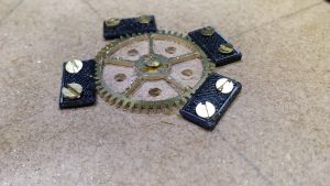
Clamps in place ready to run crossing outCrossing out completed and milling finishedFinished wheel after a light papering
What a feeling to complete it and thanks to Delph for their support in getting me there.
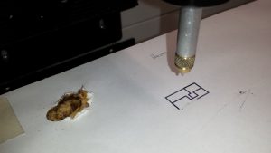
Well it had to happen …. first ding on the Tormach 440 which thankfully was not major.
I made a spring loaded pen from an old Parker Pen body and refill to allow me to sketch the XY movements of the mill on sheet of paper on the mill table. I forgot to reference the tool lengths and the pen buried itself into the table …. fortunately I had a sheet of MDF fastened to the table for protection but the pen dramatically disintegrated and distributed itself around the workshop.
A new pen has been made, better than the first one and no damage to the mill, just to my pride.
I must practice hitting the STOP button with my eyes closed.
After a lot of research and testing I managed to run a small test piece in MDF using Fusion 360 CAM imported into the Tormach 440. Hand hovered over the emergency stop button but all went well. Getting there slowly.
There are so many boxes in the CAM settings for each function that is a worry what needs ticking where. Lars Christensen‘s Part 4 video on CAM helped no end. The other one to watch that was useful was the Library tutorial.