You know only too well how I keep on going on about FlatCam and milling printed circuit boards on the Tormach PCNC440.
You will also have read about my preoccupation with trying to hold the PCB material flat to avoid variations in milling depth.
I have got it to a reasonably repeatable process using mechanical clamping but you know when a perfectionist starts something it has to be as good as possible …. step forward the Vacuum Clamping Table.
The thinking for this followed on from the Rosebud Grate experiments on my live steam locomotive. The grate consisted of a matrix of larger holes on the underside of the grate leading to a small bore hole on the top side of the grate. The theory as I understand it was that the reduction in size creates a Venturi type effect and boosts the air stream into the fire. I wondered therefore if I reversed the air flow i.e. sucked the air from the large hole into the small hole whether this would be beneficial in providing a boost of the suction. It is a bit tenuous I must admit and I can’t point to lots of science to back this up, but certainly worth a play.
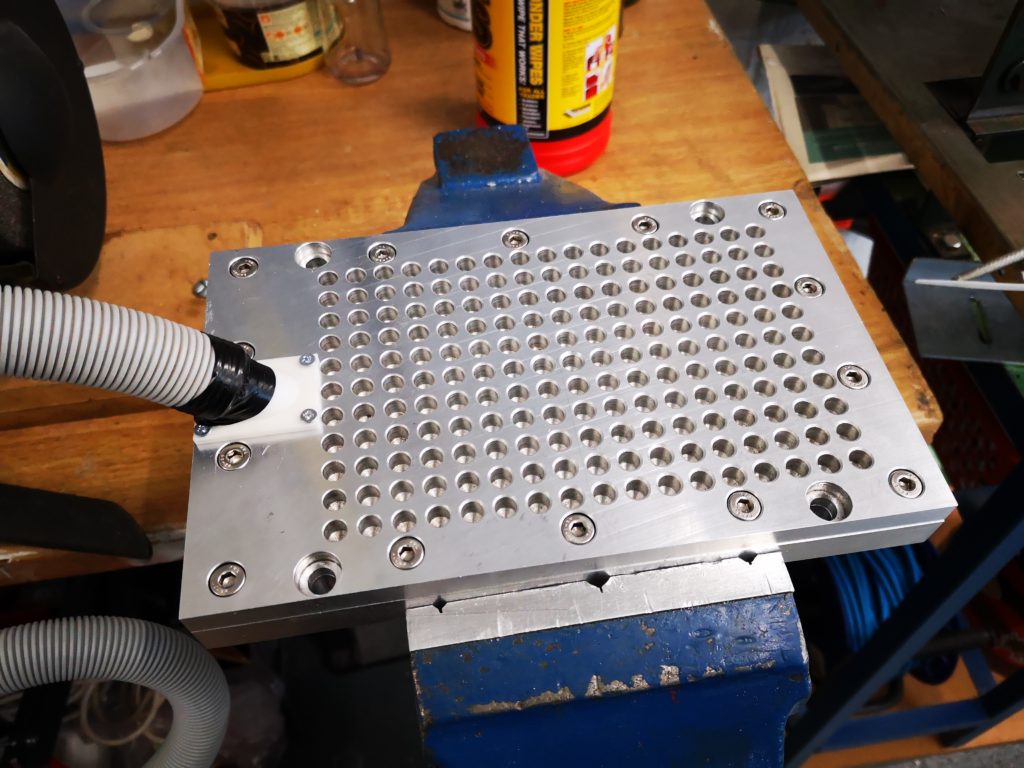
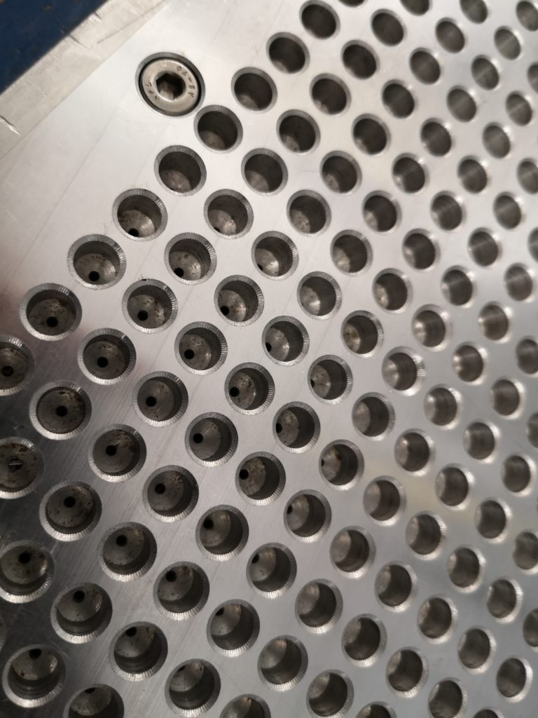
First stop was Fusion 360 and a two part plate was designed. This consisted of a top and bottom part. The bottom part is 15mm cast aluminium with a milled trough and the top plate is 10mm cast aluminium with 6.8mm holes (no science – this is tapping size for M8 that was already in a Tormach collet) on the top side that reduce down to 1.3mm holes (ditto also already in a collet) as breakthrough holes on the bottom surface. Around the edges are M6 screw holes to clamp the two plates together and also M8 mounting holes to fasten the plate to the tooling plate on the Tormach. 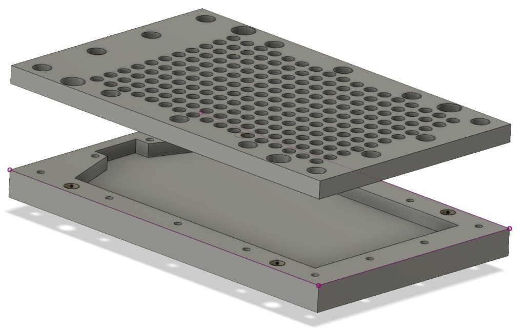 I didn’t quite think the suction connection fully. After I had worked out the total area of the 1.3mm holes I realised that to accommodate this I needed a 16mm diameter hole for the air inlet. This was not going to be possible to mount on the 25mm overall edge of the plate. The solution was to 3D print a connecting pipe and mount this on the top surface. This adapts to the vacuum cleaner pipe being used as the suction source.
 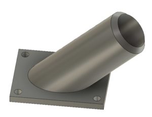 The 3D printed adapter did not provide a good seal to the top plate so I had to fit a rubber gasket on it. The parts were all put together as shown below.
To my amazement it seems to work !
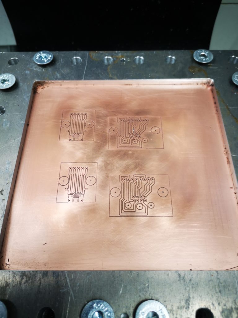
There does not seem to be leakage on the joint between the two plates and the vacuum pipe adapter with the rubber gasket seems to seal alright. If I put a large piece of PCB material over all the holes it is very difficult to move it. Single sided board is naturally bowed in the manufacturing lamination process and I can see it visibly jump flat when I turn on the vacuum. If the PCB is smaller than the total area of suction holes it does not seem to matter about covering over the ‘non-used’ holes to maintain the grip.
Proof will be when I try to run a board.
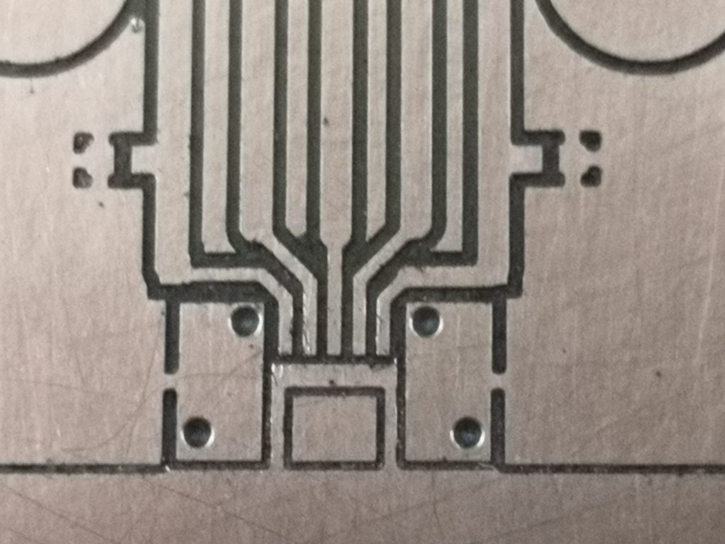
The milling process will not have major sideways pressure as the depth of milling is quite small so it should be fine. Clearly I can’t go drilling the component mounting holes in the PCB material with this holding technique but I can spot drill them to say 1mm depth and then finish them by hand having got a guide hole to start me off.
But all this will have to wait as the X axis limit switch has come apart on the Tormach and a spare has been ordered and is on its way.
UPDATE Feb 2021 – Flatcam and milling pcbs 2021 pdf download
Similar or related subjects : –
- FlatCAM installer ‘disappeared’
- Further experiments milling PCBs
- Editing irregular PCB shapes in FlatCam
- Vacuum table update for PCB milling
- Update on CNC milling printed circuit boards on a homemade vacuum table
- Experiences and understanding FlatCAM PCB milling program
- Clamping of printed circuit boards while milling tracks follow up
- A Mini Vacuum Clamping Table for PCB Engraving
- Stretching FlatCam and PCB milling on Tormach PCNC440
- Milling Circuit Boards Update
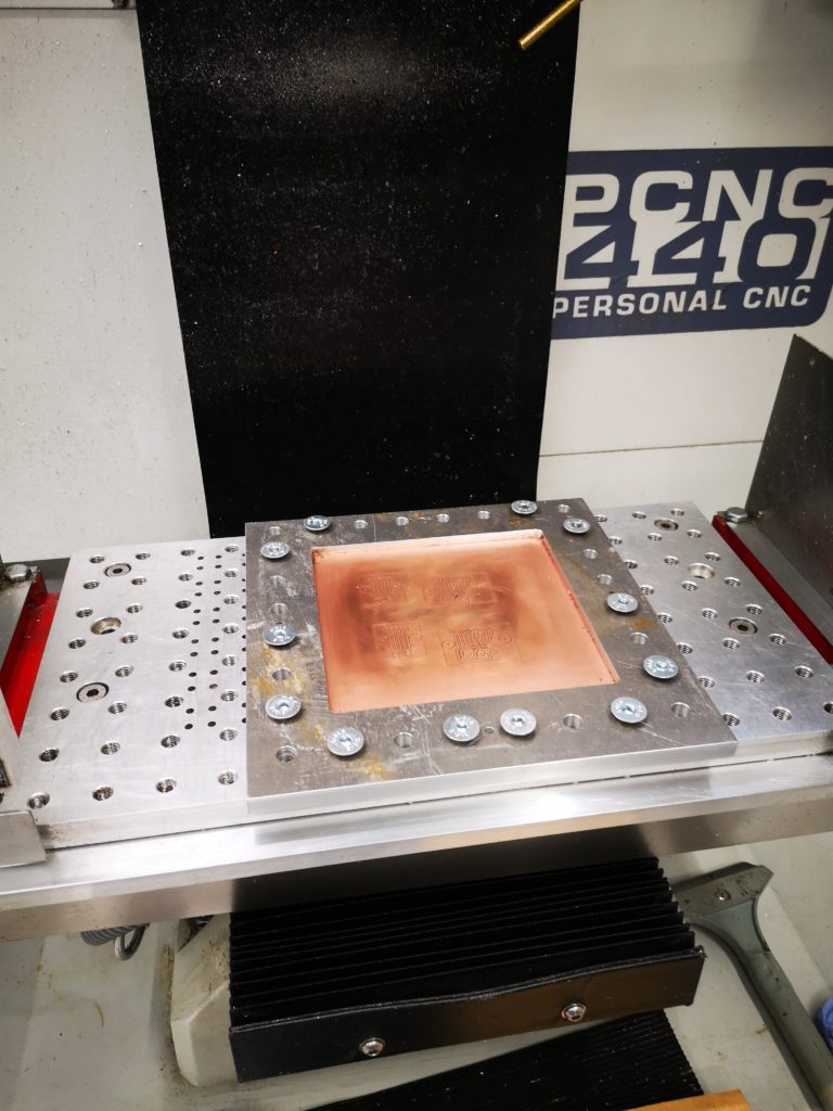
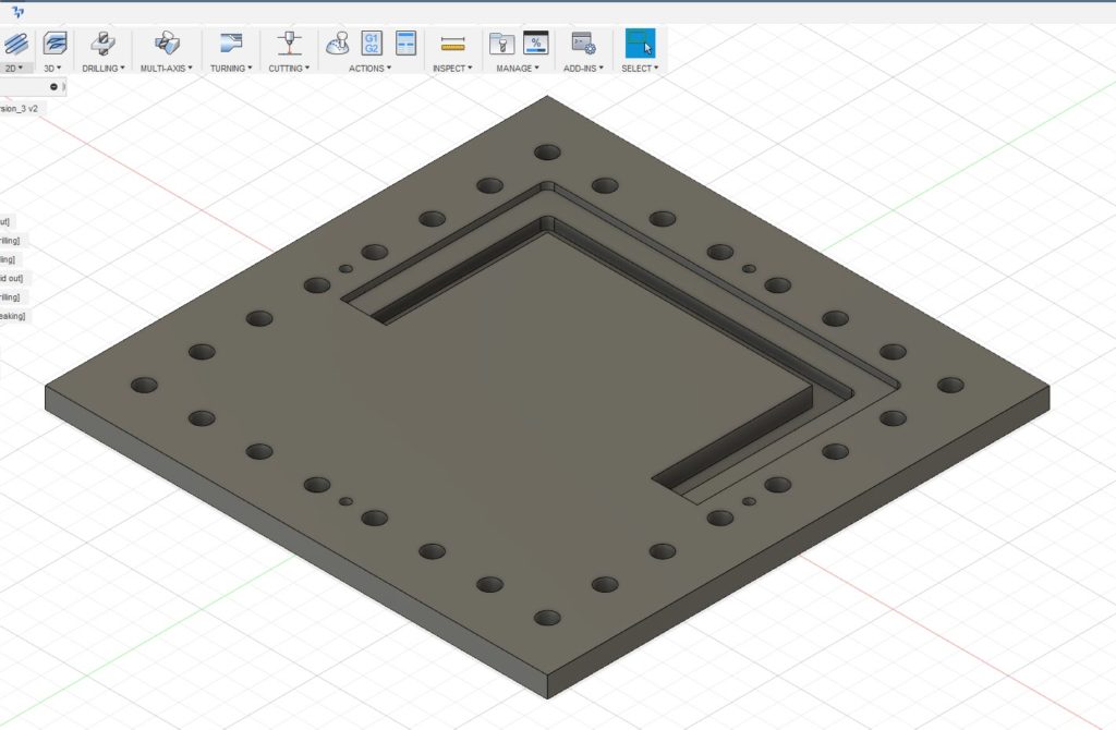 The outer holes are for the M8 clamping to the table and the four smaller holes are the tooling holes. Being tight with my materials I did not want to just mill out the centre of the plate and have a mountain of swarf (chips). Instead I designed it with two slots as shown, one for the clamping surface and one that almost cut through the stock. The partial cut was to ensure the central piece did not flip out once cut free and damage my cutter. First one half was drilled and cut and then the plate was rotated 180 degrees and the second half cut. This left the central island just held in place by less than 0.5mm of material. This was easy to hand cut through to liberate the central area. The plate was then turned over and the cut edge cleaned using the same tooling position and doing the same 180 degree rotation. To my surprise the rotation process on the tooling pins worked very well with only a minor step transition at the overlap point on all cuts. This was probably more down to my 3.7mm tooling pins being not quite concentrically turned from 4mm silver steel. With this finished I now had a much more robust clamp for the PCB material. I had made the clamping step 4mm deep so I could put sacrificial backing boards behind the PCB being run. This would allow drilling through as needed. Checking the flatness of a clamped PCB blank with my Haimer showed variation of a few thou in the top surface of the PCB Z position. The worst case variation in Z was at dead centre where the PCB’s natural bow was most dominant.