Tormach M Code Expansion Card
I have got a project underway to use the Tormach USB M Code expansion board in association with an A axis rotary table. Details of this will follow in due course. The expansion card when added to a Tormach mill allows the operator to embed M Codes in their CNC program which will operate up to 4 dry contact SPCO relays or accept 4 inputs as handshaking acks.
My Cabling Masterplan
As part of this project I need to have cables from the USB expansion board to various devices and in a rush of blood to the head decided to use standard readily available Micro USB cables for this. Now the cable connectors are pretty small and the PCB mating socket is even smaller with its 5 connections. Glibly overlooking this I asked a colleague to produce a PCB layout for the connector to a breakout connector strip. Dave duly produced a layout and a scratching of head resulted. How was I going to produce the PCB and how was I going to solder to the connections assuming I could see them ….
FlatCam to the Rescue
Elsewhere in my blog there is mention of the use of FlatCam to create a CNC GCode listing from PCB Gerber and Excellon files. This program works really well and many successful PCBs have been produced but I have never attempted to mill such fine PCB tracks. A number of problems needed to be addressed to make this successful. The PCB sheet needed to be held very flat on the PCNC440 tooling table and the correct milling tool with its associated feeds and speeds needed to be chosen. In the past I have used strips of aluminium to fasten the PCB blank down on the tooling table. This is never perfect and leads to variations in the pressure around the edges of the board. With single sided PCB there is a natural curvature of the board material as a result of the surface tension of the laminating process. A single sided blank has a concave surface on the copper side. I needed to create something more repeatable.
Milling Window Restrictions
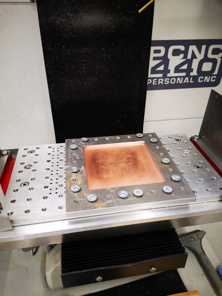
Before I bought the Tormach PCNC440 I had a discussion with John Saunders at NYC CNC and he recommended going for the biggest machine I could fit in my workshop. I could have squeezed the 770 in at a push but I would have had to sell off my Myford VMB which I was reluctant to do. My order therefore went through as a 440. With hindsight this decision has been justified on two counts. I rarely need a larger working area than the 440 offers and the VMB gets used very regularly for quick jobs that don’t justify CNC. This project was an exception. I wanted to make a frame that would clamp the PCB blank down onto the tooling table. In order to get the maximum working area for the PCB blank the clamping frame would have to sit outside the machining area. How was I going to manufacture it ? Fortunately my tooling plate was designed to have a mix of M8 clamping holes and 3.7mm tooling holes and I was going to use this to advantage. The clamping frame would be symmetrical. By adding some matching tooling holes in the frame I could cut just over half of the frame and then flip it round 180 degrees and cut the second half. Here is a picture of the CAD showing half of the machining on what will be the underside of the plate when in use. 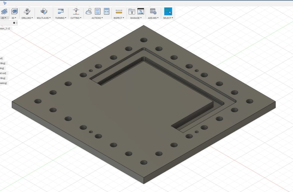 The outer holes are for the M8 clamping to the table and the four smaller holes are the tooling holes. Being tight with my materials I did not want to just mill out the centre of the plate and have a mountain of swarf (chips). Instead I designed it with two slots as shown, one for the clamping surface and one that almost cut through the stock. The partial cut was to ensure the central piece did not flip out once cut free and damage my cutter. First one half was drilled and cut and then the plate was rotated 180 degrees and the second half cut. This left the central island just held in place by less than 0.5mm of material. This was easy to hand cut through to liberate the central area. The plate was then turned over and the cut edge cleaned using the same tooling position and doing the same 180 degree rotation. To my surprise the rotation process on the tooling pins worked very well with only a minor step transition at the overlap point on all cuts. This was probably more down to my 3.7mm tooling pins being not quite concentrically turned from 4mm silver steel. With this finished I now had a much more robust clamp for the PCB material. I had made the clamping step 4mm deep so I could put sacrificial backing boards behind the PCB being run. This would allow drilling through as needed. Checking the flatness of a clamped PCB blank with my Haimer showed variation of a few thou in the top surface of the PCB Z position. The worst case variation in Z was at dead centre where the PCB’s natural bow was most dominant.
Tooling and Feeds and Speeds
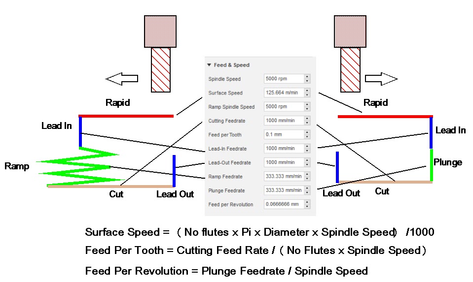
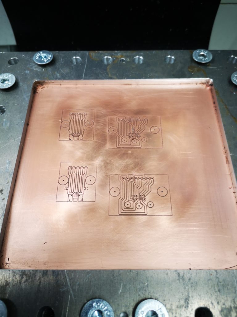
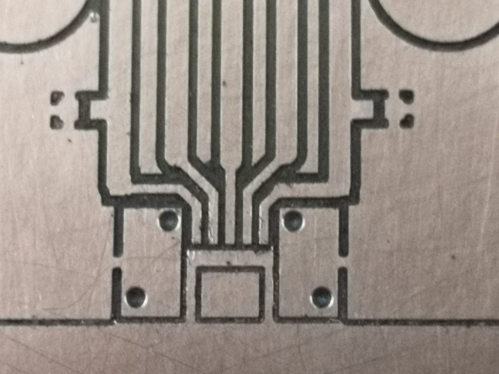
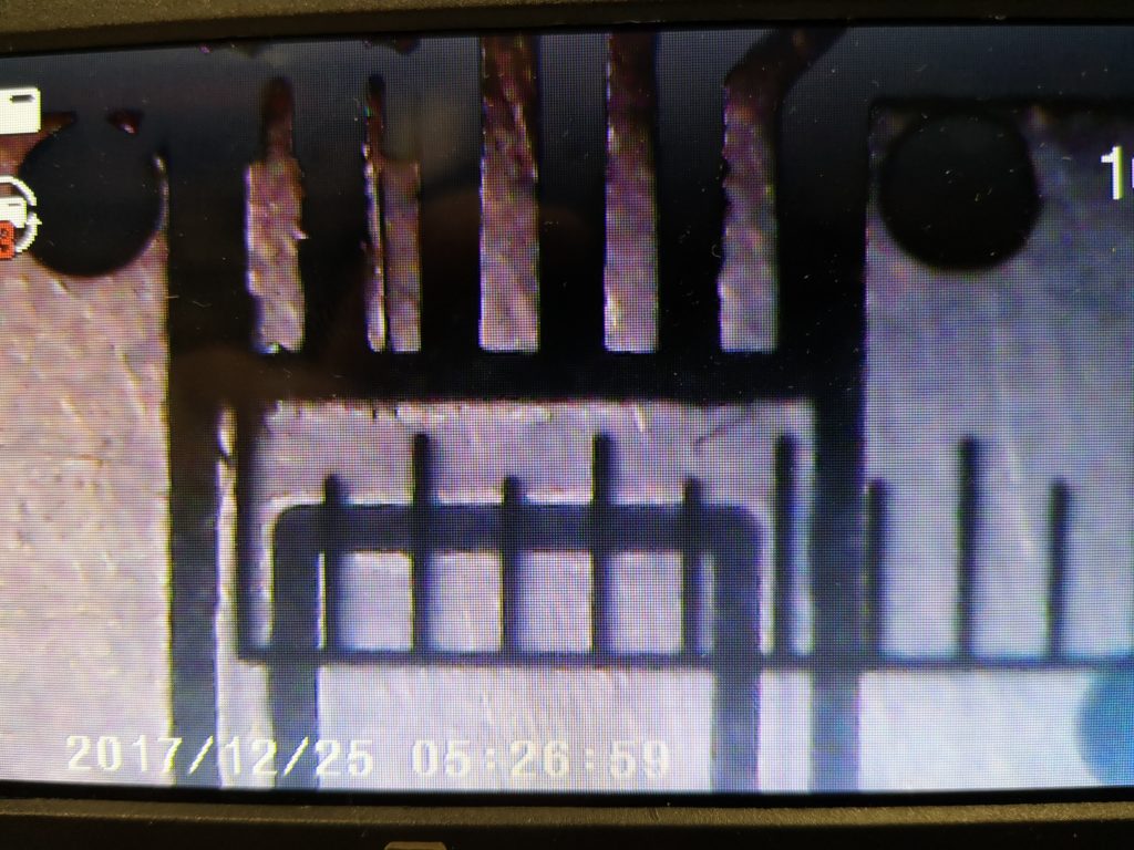
The next problem was the milling tool and feeds and speeds. I experimented with various V shaped routers but was not happy with the results. The 5 thou tip on a 10 degree V tool was incredibly fragile. Also because the tool was V shaped, any residual bow on the PCB surface lead to a variable width cut. In the end I opted for Think & Tinkers 15 degree, 2 flute tapered stub (P/N EM2E8-0051-15VC). This has a 5.1 thou cutting tip which is parallel for the first section so depth variations have no impact on the width of cut. I ran the program at 10,000 RPM (PCNC 440 maximum) and at 150mm per minute feed rate. The PCB does not look particularly beautiful after milling as there are burrs and shavings present but a gentle rub over with a fine wet and dry removes this and leaves a remarkably clean cut tracking. The images below show some of the results. The fine tracking for the USB connector connections is shown on the microscope with a scale for reference. This shows the five fingers occupying 120 thou with fairly similar track to gap widths of around 15 thou. So now I just have to solder the connectors in place …. I will let you know how it goes.
Similar or related subjects : –
- FlatCAM installer ‘disappeared’
- Further experiments milling PCBs
- Editing irregular PCB shapes in FlatCam
- Vacuum table update for PCB milling
- Update on CNC milling printed circuit boards on a homemade vacuum table
- Experiences and understanding FlatCAM PCB milling program
- Clamping of printed circuit boards while milling tracks follow up
- A Mini Vacuum Clamping Table for PCB Engraving
- Stretching FlatCam and PCB milling on Tormach PCNC440
- Milling Circuit Boards Update