It has been a quiet period leading up to Christmas and it has lead to some low level activity catching up on items on the ‘Things to Do’ list.
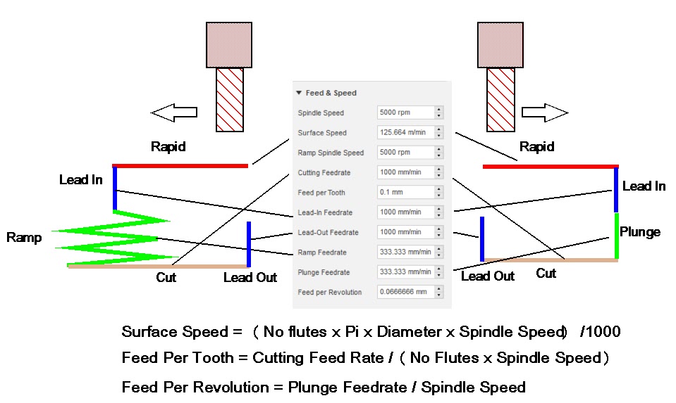
One of these was to make a graphical representation of what the Fusion 360 Feeds and Speeds dialogue box means and the calculations behind it. To be honest this tab in the Fusion CAM section used to frighten me but I have become more confident with it. The problem is I can’t remember what each box affects so here is a visual representation which might help others. Note that the dialogue changes between a ramp into the stock (such as when cutting a pocket) and a plunge into the stock (such as when drilling).
I hope that makes sense and I have got it right. It certainly helps me to understand what is going on and the calculations going on in the background.
Having got home from Chicago I had a few weeks at home before we left for Hawaii where my son was participating in the Ironman World Championships. This is a crazy triathlon event in 30 degree heat and he finished in just over 9 hours.
We played a few rounds of golf on the Makalei course on Hawaii which is at 2500 feet above sea level. Sometimes in sunshine, sometimes cloud and sometimes hissing down with rain all of which made it challenging. We also visited Pearl Harbour which was quite moving and this included visiting the Aviation Museum on Ford Field.
No visit to Hawaii by a Brit would be complete without a visit to the Captain Cook monument in Kealakekua Bay. We completely misjudged the arduous terrain we would experience in getting down to the monument and nearly came to grief with dusk fast approaching.
Captain Cook Monument Inscription Plaque in Hawaii
On the way home from Hawaii we stopped over in Seattle for a few days which was a culture shock on body temperature. We visited the Pacific Science Museum and the Space Needle plus a tour of the Boeing works as part of the stay. The PSM is brilliant for kids (and OAPs).
All in all a good trip but will now be glad to get back in the workshop.
CAD & Farming
Being away home and more precisely away from the workshop, allowed me to do a few write ups that might be of interest and both of which were stimulated by reading forum posts on MEW. My waffle would have been too long to post in the normal way.
The first write up is about CAD/CAM and my concern that there will probably be unfilled expectations from the news about Alibre doing a special deal for MEW readers.
The second write up is about harvest time in North Yorkshire that is based on my younger days in a farming family. This has been on the stocks for some time and the posting on the forum kicked me into finishing it off.
Rather than have the annual Open House at his factory in Zannesville, John Saunders at NYC CNC decided to have a joint event in Chicago at the MHUB facility under the banner of a Manufacturing Entrepreneurship Summit.
The format was for key presentations together with the attraction of having a tour of the MHUB setup which is a resource facility for product development.
John Grimsmo, a highly respected knife maker, told of his ups and downs prior to his current success. This was followed by Jay Pierson telling his not dissimilar path to his company’s success in the machining work holding market.
After a break for a tour of the facilities there was an update from AutoDesk regarding developments on their wide portfolio of engineering software with particular interest in Fusion 360. There was then a closing Q and A session.
The tour revealed the breadth and depth of the resources available to external organisations at MHUB to help get a product to market. An extensive mechanical workshop, 3D printing, electronic workbenches and software development are just a few of the tools and resources available. It was impressive.
The afternoon and evening passed quickly and it was good to see some familiar faces from my visit to last years Open House and the training course I attended in Zanesville.
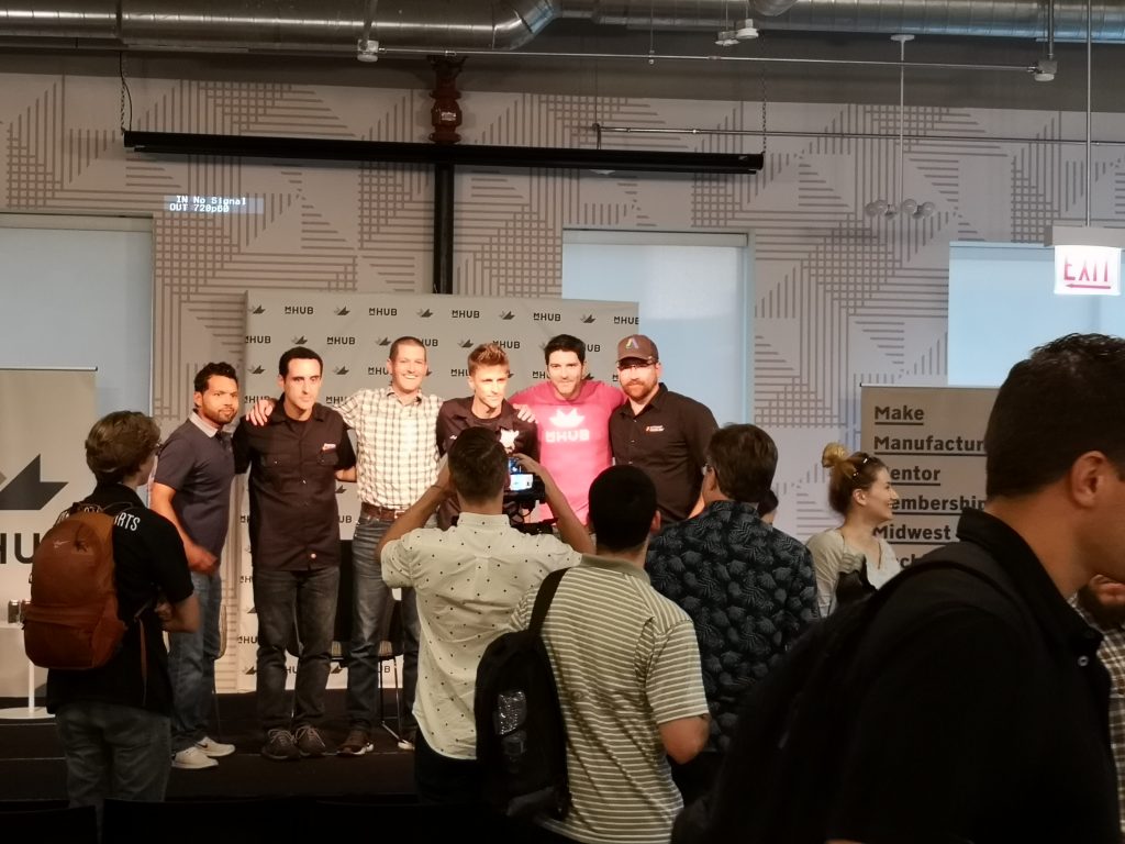
John Saunders in checked shirt flanked by Jay Pierson, John Grimsmo
As I sat listening to Jay and John I could not help but identify with how they had got to where they are and the parallels with my business days. We may be many years apart but we have all suffered the same ups and downs, long hours etc that are an essential part of getting to success.
My travel agent (aka my adorable wife) has got my airline tickets ready so I can attend John Saunders’ Open House bash at MHUB this Sunday coming in Chicago with 3 days afterwards at IMTS 2018.
Hopefully I will meet up with some of the friends I met at the NYC CNC training week and last year’s Open House plus all the new contacts that I have made via this blog. Also hoping to be blown away with seeing new technology (totally out of my budget) at IMTS.
While doing the drawings for the Rosebud grate on Fusion 360 I cheated slightly. From my measurements, I made a best estimate sketch of the needed grate size to fit the firebox floor and having drawn this up, I did a 3D print of an equivalent size thin piece of PLA. Having trial fitted this printed plate I did some trimming on the Fusion drawing ready to create the CAM.
I had bought in some 150mm square black mild steel plate and cut it roughly to width but left the length at 150mm this being longer than needed. This allowed me to clamp the ends of the stock to my tooling plate on a piece of MDF. I had one clean cut edge on the cut stock to use as a reference. When mounted I checked this with the Haimer to make sure it was running parallel in the X plane. Note I cut the MDF to roughly the same size as the plate so as not to interfere with the clamping.
I did a PathPilot width and length measure using the Haimer and found the centre of the plate and set this as G54. My Fusion drawing and CAM were referenced to centre. I was now ready to go.
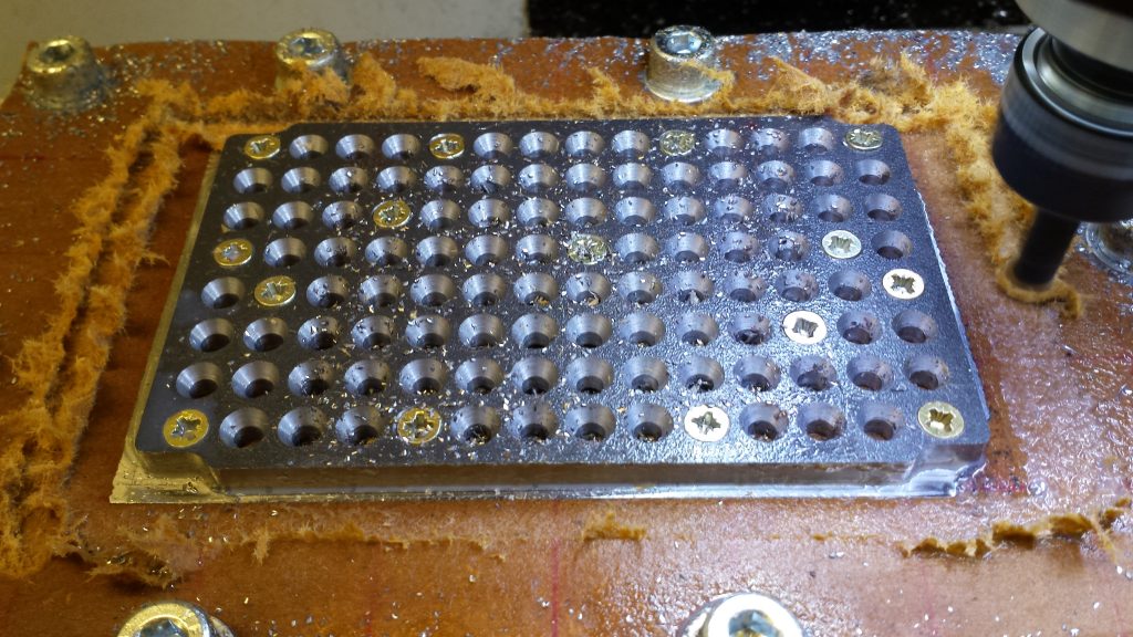
First operation was to spot the matrix of holes and the second op was to drill them out to 4.1mm. Third op was to countersink the holes to 3mm depth. This was a bit interactive. I just worked on one hole only to start with and did repeated cuts using a BS3 countersink until the depth was correct. I then did a ‘chose similar size’ selection in Fusion CAM and then ran the full op.
This now left machining of the profile of the plate to the size of the fire box floor dimensions as per the CAM and my dummy PLA plate.
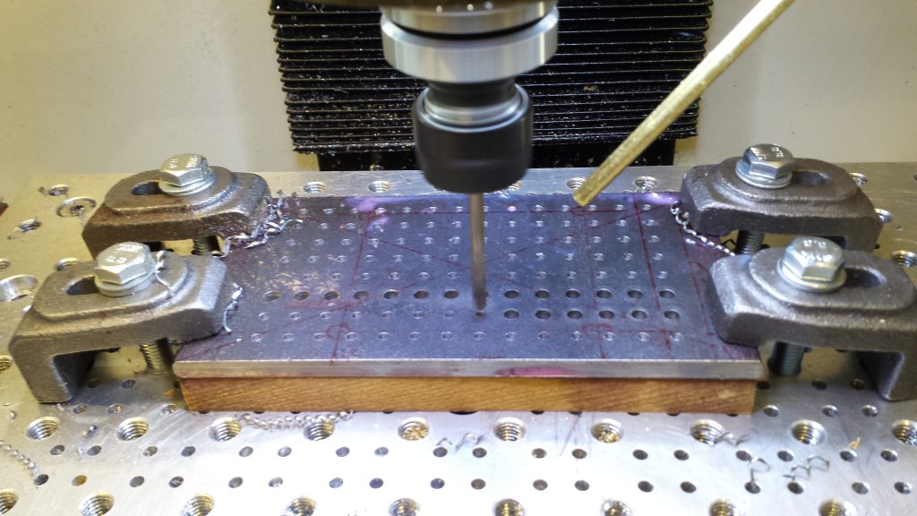
First Ops on the Grate, spot drilling and then hole drilling. Note the clamps on the outside of the plate area.
Clearly the clamps were now a problem as the end areas were excess material on the length. To get round this I removed the drilled plate from the MDF (the MDF had already started to degrade and swell with the cutting fluid) and mounted a new piece of MDF on the tooling plate with M8 fixings. As you will see below I went a bit OTT with these …. there is even a hidden countersink one under the plate to stop the MDF bowing upwards …
I remounted the grate on the new MDF with a single woodscrew in one of the grate holes and checked and adjusted the angle of the plate so the good edge was running true in X as before. I then added a ‘sprinkling’ of more wood screws so the plate was firmly in position and running true. I then re-referenced G54 to the centre of the grate as before.
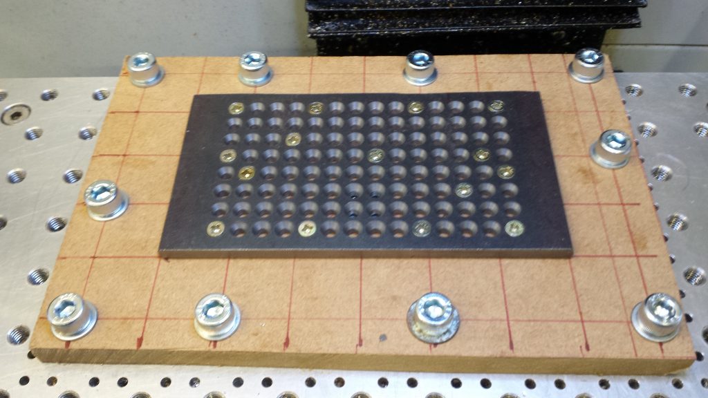
Plate remounted on a new MDF backing plate and held in place with randomly placed wood screws using the grate hole matrix.
Now I hate making swarf (chips) of material if it is not necessary … so having got the plate securely in place on the MDF I then took it off again and cut off the excess material on each end of the length. Sad really but you never know when you might need a couple of small pieces of steel …
The grate could now be mounted back on the MDF with the plethora of screws positioning it back as before. I did re-check with the Haimer and also rechecked the Z height once again.
The CAM adaptive profiling was with an 8mm cutter. Obviously I was cutting air at each end of the grate where the stock was now missing but not a problem.
Profiling almost complete. The MDF is starting to degrade and swell.
I could have used a super glue and masking tape holding method but the black mild steel does not have a smooth surface like BMS and I was doubtful how well it would hold. With hindsight the method I adopted did give me some flexibility in the process method.
The final process on the Myford Super 7 was to make four posts to sit the grate at the correct height spacing above the ash pan to match the old bar grate position. These posts were fixed onto the grate by sacrificing four of the holes. This of course reduces the hole count and therefore the hole area percentage occupancy from 15.17% to 14.62% – but not worth worrying about.
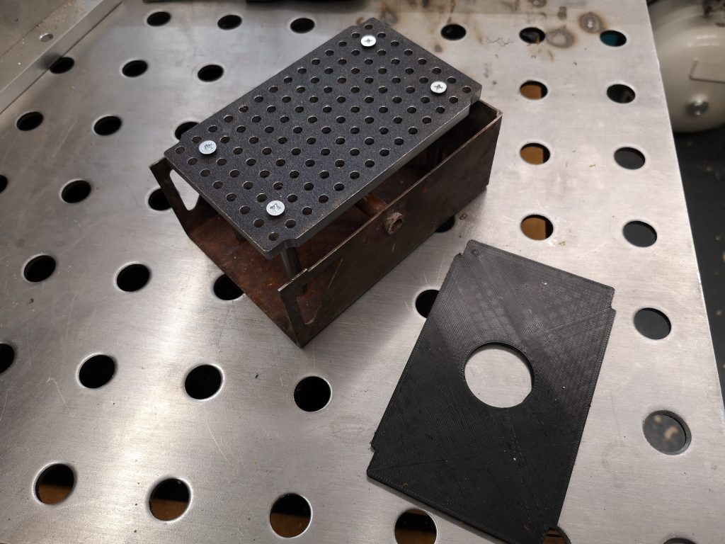
Finished grate standing in the ash pan and also the 3D printed test shape
So now I have to prove that all this effort was worthwhile and the grate will make a difference to the Polly V steaming. More to follow on this in due course. We have had some rain over the past couple of days so the Club track will no doubt be open for steaming in the near future.