Useful 3D printed adapters for hand tapping 3D threads
I usually 3D print all threaded holes as a modelled thread rather than tapping drill size hole which would need full post print tapping. As the intended thread size of modelled threads reduces so the print quality of the thread can be a problem. This usually leads to a quick post print run through the thread with a manual tap.
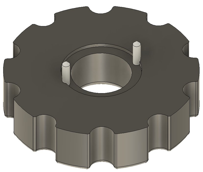
Thread quality and strength can be improved by increasing the number of perimeter prints via the slicer software. This makes the printer add extra print lines around all external surfaces before it does the infill. This is even more important if you are going to use brass inserts for your threaded mountings as it gives the insert more plastic to melt into.
The problem with post print clean up tapping is getting the tap to start perpendicular to the already printed tapped hole. If the hole is small (say M2) the size and mass of the tap holder adds to the wobble difficulty of getting it ‘plumb’.
In the past I would mount the tap in a small toolmakers chuck as this gave an extended length to the tap for the eye to judge the ‘plumbness’. I didn’t have enough chucks with the right size collet to cover all tap shanks.
Some time ago Clough42 recommended a small electric screwdriver that had 4mm AF inserts. I found this one on Amazon. There are also many other electrical and manual screwdrivers that use the 4mm AF insert standard.

It struck me that if I could make a set of adapters to mount in the screwdriver chuck to hold the tap shank this would ease the post print tapping problem. The length of this particular screwdriver body gave a better ‘to the eye’ perpendicular check. The added ability to electrically drive the tap meant that the perpendicular setting was more easily maintained. The speed and torque of the driver would also act as a break clutch.
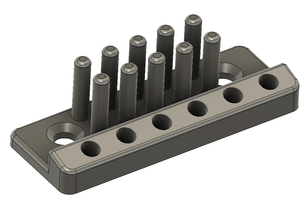
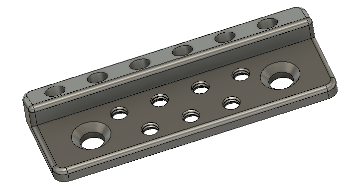
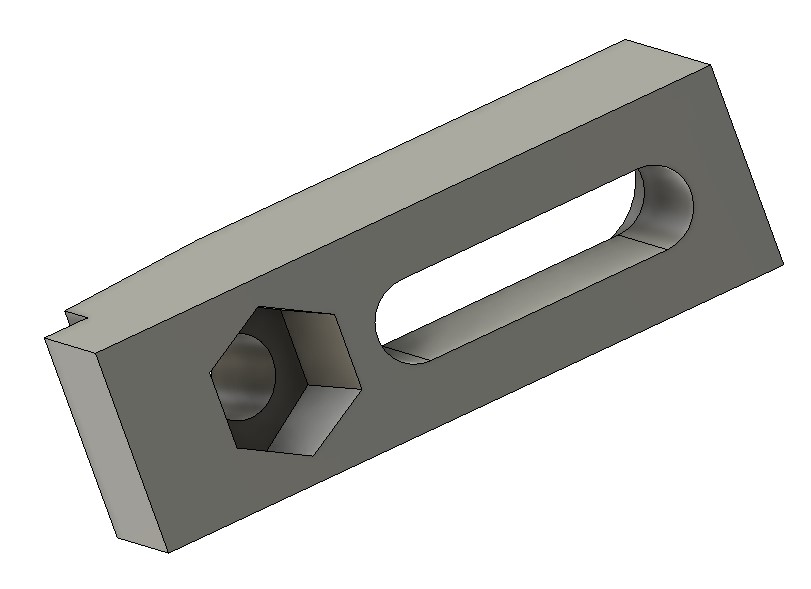
I debated a lathe activity but then thought why not a 3D print? I created a model in Fusion with Parametric functions for the tap AF dimension and square driving section length.
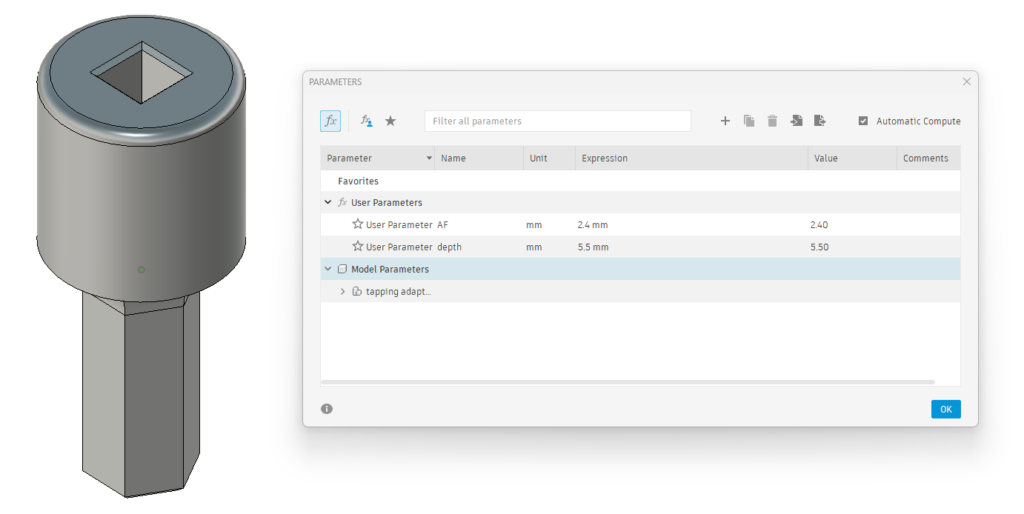
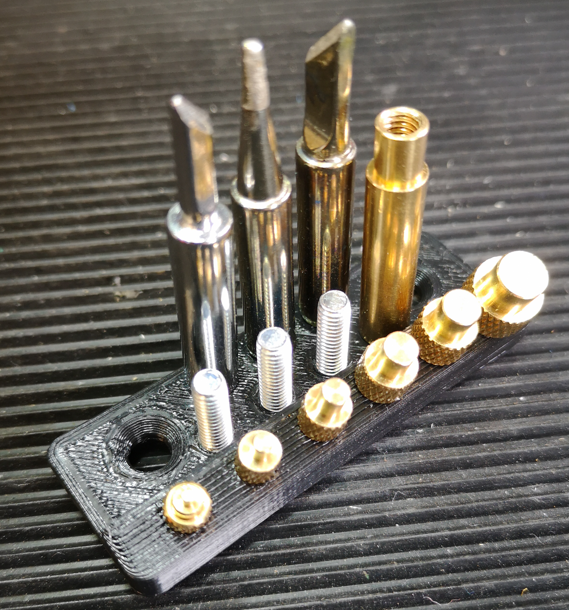
Not all taps are created equal so these two parameters can be easily adjusted using the parametric function to match your tap sizes. Print time was around 9 minutes on my Qidi X Smart. I printed the adapters in PLA+ vertically off the bed as shown and in 0.2mm layer height. I set the slicer for 6 perimeters on the print, a 6mm wide outer brim for build stability and auto support off the build plate.
The adapter boss section will accomodate up to M5 size tap shank dimensions (3.9mm AF, 8mm length). Any size greater than M5 will usually print very clean and not need post print fettling.
Here is the Fusion file for those interested.
Links to similar or related post are listed below : –
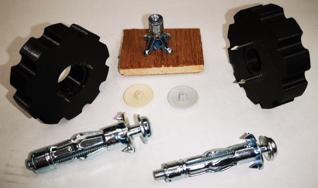
- Hybrid 3D brass threaded insert tool
- Tap shank adapter for 4mm AF hex drivers
- Qidi Slicer auto support error on my part
- Qidi X Smart 3 revised fan installation
- Qidi X Smart 3 tweaks
- Qidi X Smart 3 special weekend pricing
- Stop losing Qidi ifast 3D prints down the chamber front gap
- Fitting a Bento air filter to a Qidi ifast 3D printer
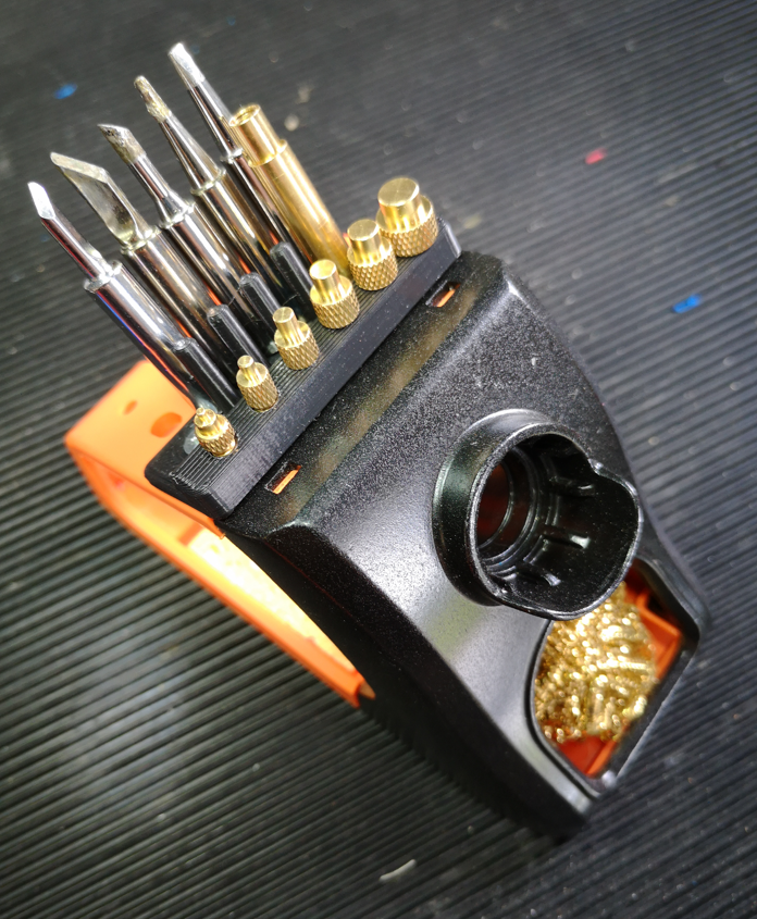
- 3D Printed Brass Threaded Insert Soldering Iron Stand
- eSUN filament reel silica drying pod