TLC for the Polly V
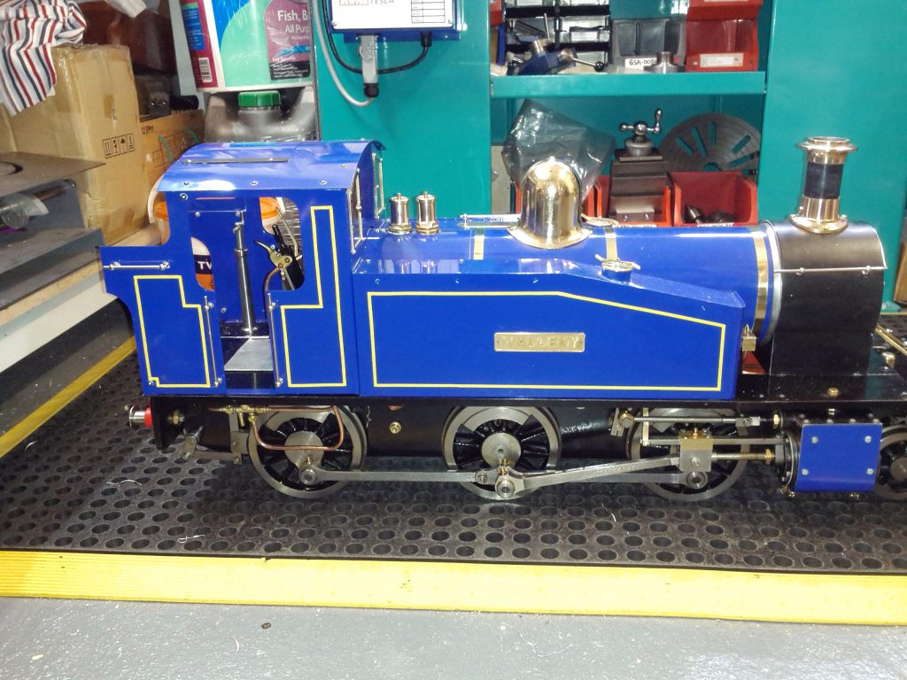
I have been the owner of a Polly V 5″ gauge locomotive for some time now. It has run OK but I have always had some unexplained happenings with it. Things like being reluctant to start and sounding ‘out of balance’ to use a clock making term. I also admit that while I know the overview of how it works I have never got to grips with Stephenson Valve Gear. I decided that some investigation was needed.
New Piston Rings
A bought a new pair of O rings for the cylinders a few weeks ago and decided it was time to fit these as a first step in an engine health check. This was easier to do than I expected. The end face of each cylinder is held in place with eight hex head screws and when these are removed the end plate can be taken off. The cylinder rod can be disconnected and the piston pushed out of the end sufficiently to swap out the O rings. A liberal coating of silicon grease on the new O ring allows the piston to be gently squeezed back into the cylinder and job done. Having completed this exercise I was feeling a bit more confident.
The Stephenson Link
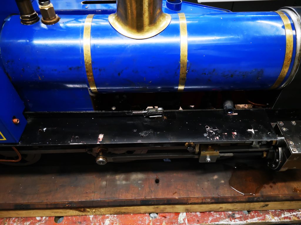
Out of curiosity I decided to have a look inside the valve chests on top of the cylinders. These were a bit more fiddly to get at as I had to remove some of the chassis work but not a major problem. On the bottom face of each valve chamber are two slots. These slots allow steam in and out / to and from the piston cylinder. The timing block moves back and forth across these openings to alternately allow steam in and out of the piston chamber. The movement of the block is controlled by mechanical linkage and each cylinder is out of phase with the other to balance the drive to the wheels.
Having opened the two chests I noticed that both looked to be set up in a different way and as I rolled the engine up and down on the bench the openings in the bottom face of the chest were not revealed in a synchronised manner. Some investigation was needed.
When I bought the engine I also got a full set of the construction notes supplied with it from which the previous owner assembled it from new. I found these notes difficult to follow which was due to the fact that I was not conversant with the names of the individual parts mentioned. I stuck with it and the first thing that struck me as wrong was the gap at the end of the Stephenson Link was not the same in ‘Forward’ and ‘Reverse’ settings on the quadrant reverser. I had no idea why this was important and no idea of this was an absolute gap size that was needed (an actual measured distance) or just a relative similar size. Clearly it was not either of these and I needed to adjust it.
Much gloom followed as I realised the adjustment for this was behind the side water tank. This would have to come off. This looked fairly straightforward except the injector water feed is coupled into this tank in the cab area. The gland nut holding this is inside the water tank and a real pain to unfasten. The amount of arc that is possible to apply to the nut is very restricted. Eventually I managed to free this and the tank came away to reveal the quadrant rod adjuster. It was then a two minute job to adjust the quadrant rod length to balance up the end gaps on the Stephenson link in Forward and Reverse.
Timing the Valve Gear
Having balanced the Stephenson Link, the next step was to adjust the valve blocks. I put the quadrant reverser at its Centre position and rolled the engine up and down on the bench watching each valve block move. The movement of each block was not symmetrical . In the Centre position the block should only just move a small amount back and forth to just reveal the two port openings in the base of the chamber.
This is easy to adjust by removing the valve actuating link arm screw. After some back and form adjusting I got the blocks to achieve the minimal movement needed about the centre position.
If I now rolled the engine back and forth on the bench in ‘Forward’ or ‘Reverse’ the movement of the blocks increased to reveal the full area of the two ports and with each side of the engine leading in turn. I now had a nice action of the valve blocks alternately opening and closing over the front and back ports with no excessive movement. Things looked much better. I cleaned up the valve chamber lid and fitted a new gasket to each chamber. I put the engine on the rolling road and using compressed air ran the engine up. Wonderful ! It now sounded more balanced and was much happier to start in Forward or Backwards. Here is a pictorial representation of the valve action.

Without the balancing in the Stephenson Link this would not have been possible to achieve.
The Eccentrics
While delving around on the underside I noticed that one of the eccentrics had movement on it and the eccentric arms were sloppy. On the Polly kit the eccentrics are positioned with a grub screw into pre-drilled holes on the axle.
Another major gloom session ensued as it looked at first sight that the boiler would have to come off to work on the eccentric arms. However after playing with positioning of the eccentrics I found I could get the clamping screws out, drop the arms off and so allow tightening of the grub screws. In the process of doing this I found that there were tiny packing pieces between the faces of the eccentric arm halves. Clearly the original owner must have believed the eccentric arms were too tight and had packed them out. I did a trial fit without the packing and the eccentrics ran freely. Perhaps this had been done as a running in adjustment. On completion I did a second run on compressed air with no obvious issues.
Putting it back together
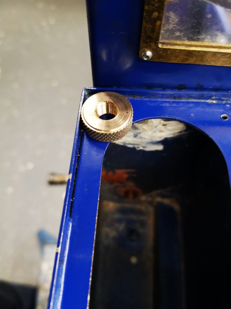
Re-assembling the chassis work was straightforward except replacing the side tank water feed to the injector. The original nut had been mangled by the previous owner so needed replacing. Rather than just fitting another hex nut I made a brass knurled nut. In the confines of the side tank this gave me better grip with my finger ends to tighten the fitting. Once it was finger tight I could use the end of a screwdriver to increment it tighter using the knurling surface to give me purchase.
Other work
While having grease embedded under my finger nails I did a few other jobs on the engine.
The whistle valve had always leaked steam and I had bought in a new version of this with a stronger spring action. This was fitted along with a new steam valve feeding the injector.
I re-positioned the pressure gauge to be central in the cab rather than off to one side as originally fitted.
I fitted a new set of drain cocks on the cylinders.
Finally I adjusted the cylinder lubricator which had been a bit too liberal with its feed delivering a snotty chimney edge and a fine mist of oil to my face while driving. The adjustment screw was unlocked and moved back a small amount.
All back together and a good days work. A lot learned which is always a bonus and less fear of the black art of steam engines.
The next day I took the engine down to the club track and made quite a few circuits on the raised level track. The engine sounded and ran quite differently. It ran much better on lower levels of steam pressure. I also did not get a bath of lubricating oil but judging by the edge of the chimney there was still sufficient being passed into the cylinders.
Similar or related subjects : –
- Swiss Vapeur Parc Festival Week
- 3D Printed Jigs to the rescue
- Rosebud Fire Grate on a Silvercrest BR Class 4
- Simple Water Level Sensor for Live Steam Locos
- French Model Steam Engine Gathering
- Replacement Whistle on Polly V Steam Engine
- Bad day steaming with my 5″ Polly V live steam locomotive
- Lempor Nozzle added to Poly V 5″ steam locomotive
- Setting up the timing on a Polly V locomotive
- Halloween Steaming of the Polly
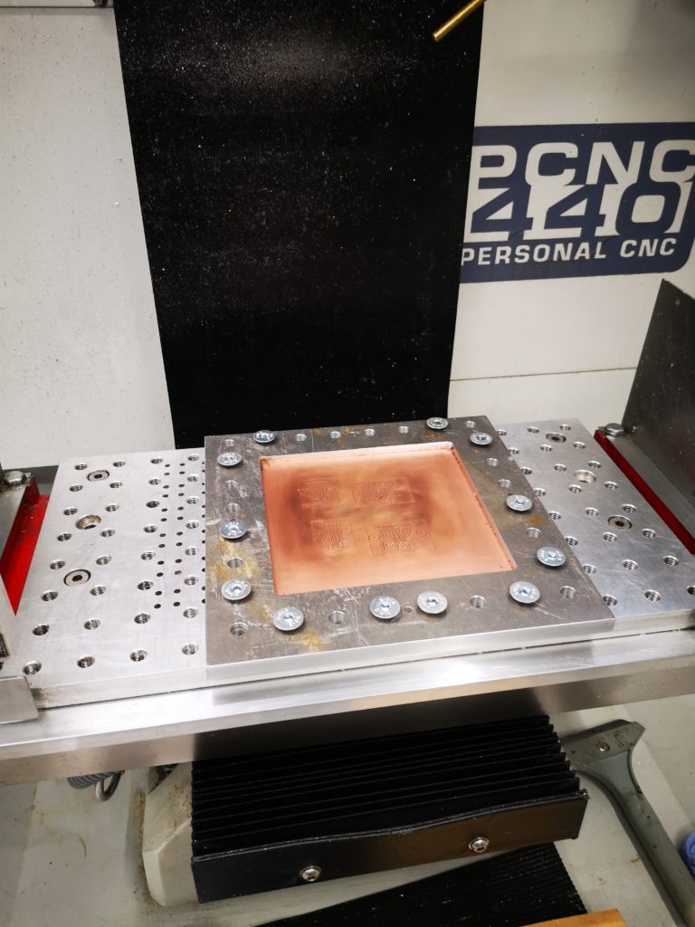
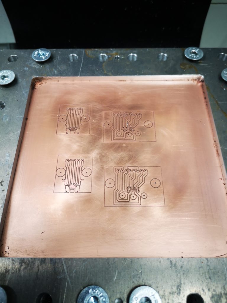
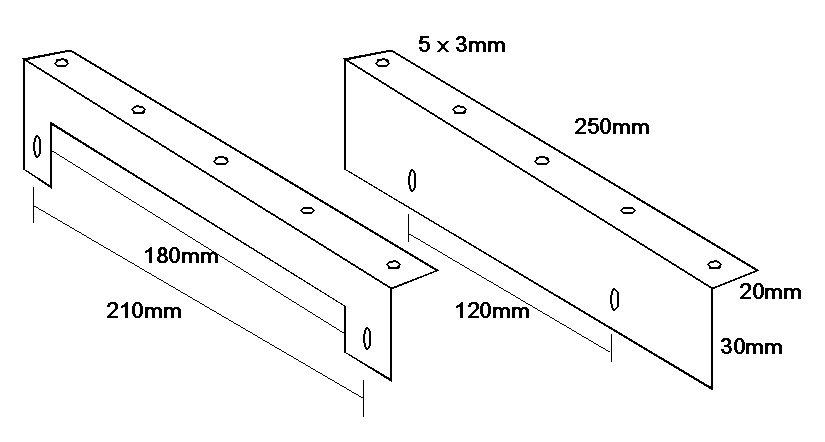
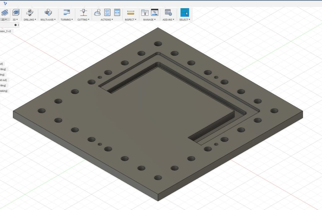 The outer holes are for the M8 clamping to the table and the four smaller holes are the tooling holes. Being tight with my materials I did not want to just mill out the centre of the plate and have a mountain of swarf (chips). Instead I designed it with two slots as shown, one for the clamping surface and one that almost cut through the stock. The partial cut was to ensure the central piece did not flip out once cut free and damage my cutter. First one half was drilled and cut and then the plate was rotated 180 degrees and the second half cut. This left the central island just held in place by less than 0.5mm of material. This was easy to hand cut through to liberate the central area. The plate was then turned over and the cut edge cleaned using the same tooling position and doing the same 180 degree rotation. To my surprise the rotation process on the tooling pins worked very well with only a minor step transition at the overlap point on all cuts. This was probably more down to my 3.7mm tooling pins being not quite concentrically turned from 4mm silver steel. With this finished I now had a much more robust clamp for the PCB material. I had made the clamping step 4mm deep so I could put sacrificial backing boards behind the PCB being run. This would allow drilling through as needed. Checking the flatness of a clamped PCB blank with my Haimer showed variation of a few thou in the top surface of the PCB Z position. The worst case variation in Z was at dead centre where the PCB’s natural bow was most dominant.