We were very lucky to be invited to this event near Cahors. A significant number of the engines were Polly designs and the owner of the track has had a long standing relationship with Polly Model Engineering.
The track has two loops and a very significant incline which tested not just the engines but also the drivers. One very encouraging aspect of the weekend was the number of young people, both male and female who were enjoying driving the track.
Links to similar or related post are listed below : –
How to create irregular outline cut paths and board cut outs
Following a request from a subscriber I have edited my FlatCam tutorial document to include a section on how to profile irregular board layouts and boards with cut out areas. The attached ZIP file contains the new version of the write up and a short video clip showing the board outline editing process.
After seeing various ideas for a filament reel desiccant holder, I decided the concept seemed like a good idea.
As mentioned in previous posts, I am now using open source filament in my Sindoh printer and my Qidi. The filament is fed from a ‘hot box’ via a 4mm OD/2mmID PTFE tube into the Sindoh or the Qidi. The ‘hot box’ is not continuously powered but is just switched on occasionally to provide background drying. By adding a desiccant holder fitted into the reel centre hole, the background moisture level can be better controlled between powered heating sessions.
I have settled on using eSUN PLA filament and I modelled my desiccant holder specifically to fit the eSUN reel size. The Fusion 360 model for the silica holder is designed using Fusion Parameters. For those familiar with this Fusion facility, you can use the FX functions to customise the size of the holder to suit other reel sizes.
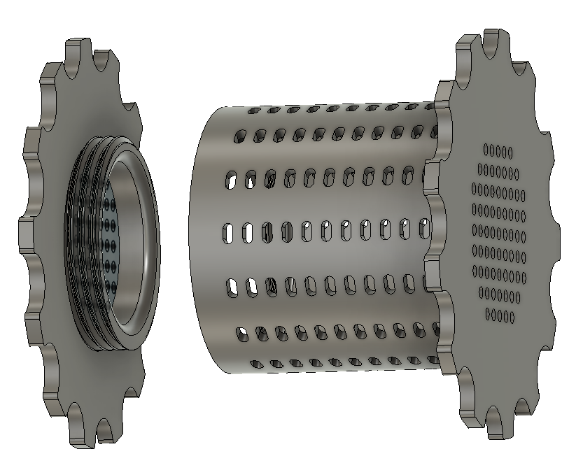
This finished holder is shown below.
The holder has two parts, the cavity and the end cap. The end cap is screwed and held in place with a print modelled 11tpi BSP thread. Both parts are printed with the large gripping flange face down on the bed. Slicer generated internal support will be needed for the overhanging threaded flange at the top of the cavity. After printing, inspect the two threads and where needed clean off any flash PLA. My prints meshed without any aftercare.
Note that while I have put ventilation slots in the barrel sides, these are probably not so effective once the holder is mounted into the reel centre. This leaves the end holes as the dominant air path. To help the air circulation in the latest download I have added additional holes on the end flanges (not shown in image above).
The desiccant can either be left in its supplied pouches or can be poured directly into the core cavity. Note that if the silica crystals are tipped lose into the cavity, the model will initially act as a sieve with any broken pieces of crystal falling out of the holes. If you are using lose crystals, don’t overfill the cavity. This will allow the natural printing revolution of the reel to cause the crystals to tumble in the cavity. This provides a more even exposure to the air.
You can buy bulk quantities of silica crystals that change colour with moisture absorption content. When dry they appear to be clear or orange and change to green when moist.
UPDATE – Linked below is a ZIP file containing the Fusion 360 file for the desiccant holder and the screw on lid. James at Clough42 gave me some pointers on this. The updated file uses the Fusion parametric functions (Fx) so that the depth of the gel holder can be changed to suit the width of the filament reel. Just change the Barrel_Length value to match the width of the reel in use.
Also in the ZIP are the STL files for a 68mm width holder and associated lid This will suite the width of most 1kg filament reels.
I recently posted about the conversion of our Sindoh 3DWOX 3D printers to allow open source filament use. One benefit of the conversion is that it allows the filament reel to sit in an external reel box such as a ‘hot box’ dryer from where it is fed direct into the printer. This has resulted in filament being fed much more reliable than it had been using the printer internal cassette system.
On my setup I had a couple of clangs where the exposed filament between the ‘hot box’ and the printer got knocked and damaged. My solution to this has been to 3D print two filament interfaces to allow a PTFE protective feed tube to be used.
The first of these printed interfaces is a push fit into the Sindoh printed adapter. The Sindoh adapter performs two functions in the absence of the printer cassette. It provides a guide to feed the filament into the printer and also overrides the filament detector flap. The filament feed aperture in the Sindoh adapter is quite wide and I designed my printed part to push into their guide and provide a 2mm feed hole to more accurately ‘aim’ the filament. This feed hole enlarges to a 4mm section that is a push fit grip on 4mm PTFE tube. Note that dependent on print quality you might have to open out this hole and the 2mm hole to suit the OD of the PTFE tube and the filament. Be careful as the 4mm section does not go all the way through the print leaving a short inner 2mm section.
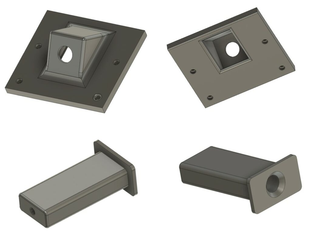
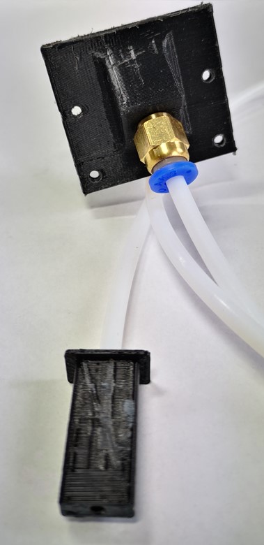
The 3D printed adapter on the ‘hot box’ mounts a M6 threaded pneumatic fitting that grips the end of the PTFE tube. This is fixed over the existing ‘hot box’ exit hole and aims the PTFE tube exit downwards. I drilled and tapped four M3 mounting holes in the plastic wall of the box base wall to mount the adapter. It sits straddling the base/lid interface line. This allows the box lid to still be opened. The images below show the Fusion screen shots and the final connected assembly.
The solution works very well. The length of PTFE tube can be tweaked to suit the physical relationship between the printer and the ‘hot box’. The tube also gives added moisture protection to the filament when it could be exposed to humid air between printer runs.
These two small adapters have made the filament feed much more professional and the new arrangement has removed the danger of accidental filament damage.
The only problem with external feed to the Sindoh is that the door on the printer can no longer be closed so I need to work on a plan where to drill a suitable slot in the door….
The link below is a ZIP file with the associated files as both Fusion 360 and STLs plus the Sindoh open filament adapter files which were part of the Open Source documentation.
A handy reference for Fusion 360 parameter functions
Fusion 360 has an incredibly useful facility whereby you can make a model dimensions fully flexible through not entering fixed dimensions but instead make them a calculation. The calculation will be dependent on other attributes of the model in conjunction with mathematical functions.
I had two problems in a recent model. The first one was where I had a dimension that I wanted to convert into a plain value rather than being associated with mm. This would allow it to be used in an equation. The second problem was needing to round a calculation result down to the nearest whole number.
The answer to the first problem was simple and obvious – divide the value in units by one unit. So something 200mm long becomes just plain old 200 when divided by 1mm. I was a bit red faced on that one.
On the second problem I searched everywhere in the Autodesk forums and found people mentioning ‘floor’ ‘ceil’ and ’round’ but it took a lot of searching to find a tabulated reference for the workings of the Parameter functions.
Having found the lookup details on the Autodesk site I have transcribed this into Woody speak which you can download as a pdf below and I have also added it to my Workshop Spreadsheet and there is a link to the latest version also below.