There are quite a few entries on my blog regarding using FlatCAM to convert PCB design software manufacturing files into CNC code. I also have mentioned my small home made vacuum table and a floating foot compression device both for holding the PCB blank flat while the milling takes place.
I have revised my original write up to focus on FlatCAM version 8.991 and also pulled together notes on these other techniques. If you like it let me know. If there are mistakes also let me know.
My wife has presented me with a sign that has just got JSN written on it. It is to remind me when I answer the phone to a ‘can you just do’ enquiry…… to Just Say No.
I try my best to live up to her expectations but sometimes something comes along that should really be a JSN job but which scratches an itch. You know what I mean. You think about it and you do all the right mental arithmetic in your head and the answer keeps coming back to the same – don’t even think about it. But the the other side of my brain is screaming at me … what a challenge, what a learning experience, what fun to have a go at it. Providing the asking party is aware of your thought process or lack of it and accepts that it might just go belly up and never come to fruition then why not ?
Back to the story – 10 days or so ago I had a call from David Pawley who is a turret clock expert extraordinaire to say someone he knew was after an escape wheel for a turret clock and was desperate. David passed on the details and a couple of days later the potential customer arrived on our driveway. After a suitably socially distant conversation and a rubber gloves inspection of the old damaged wheel …. I got sucked in and turned the JSN sign over to face the wall.
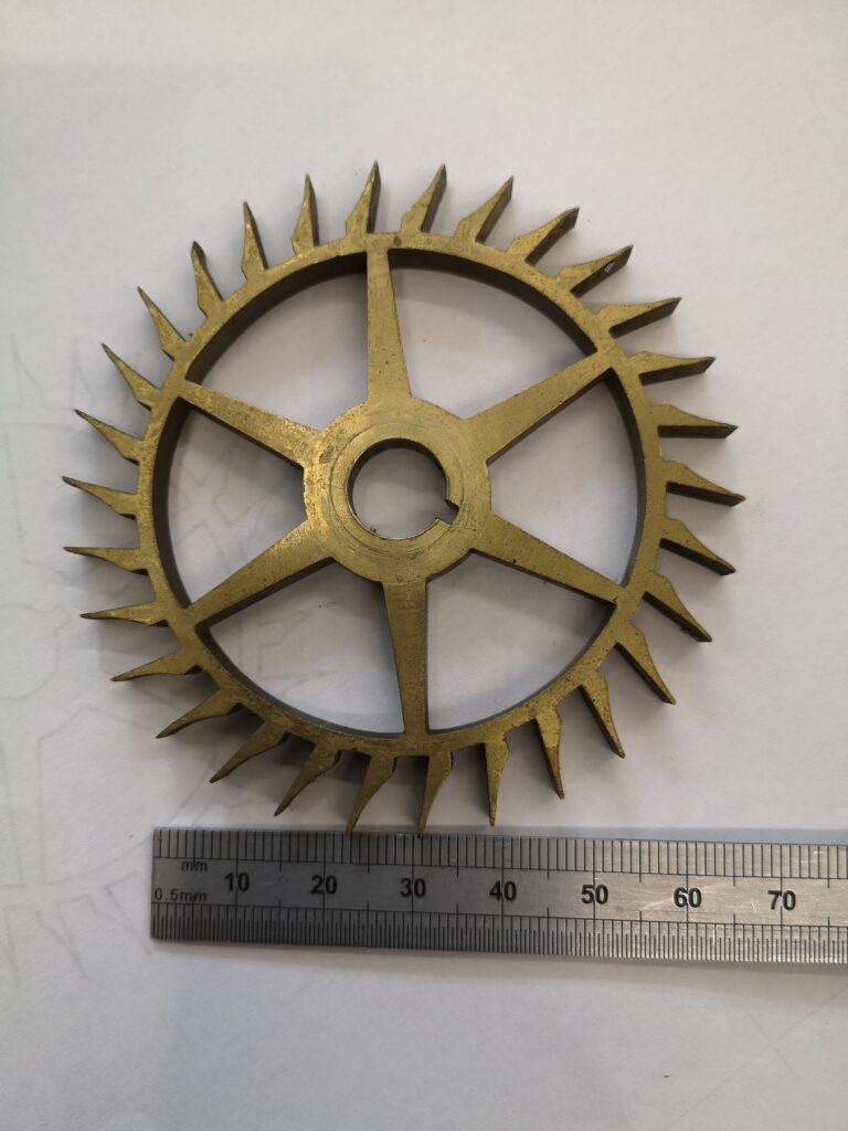
The original Brocot 30 tooth escape wheel that needed a new one making
As you can see it is not an ordinary escape wheel and I had to delve into one of my favourite books ‘Wheel and Pinion Cutting in Horology’ by J Malcolm Wild FBHI in order to learn about Brocot Escape wheels. Malcolm is a great guy and his book should be on any clock experimenters bookcase.
The Brocot is no ordinary escape wheel. In fact it is a real challenge. Not a simple fly cutter job. Traditionally it would be cut in an indexing device such as a lathe with two different cutters, one for the curve and one for the notch. I didn’t have these so I thought I would probably upset the traditionalists and try to use CNC.
Sorry that things have been quiet but we have been on a 6 week trip to New Zealand. It was the only country that my wife and I both had heard so much about and both agreed we wanted to see. So I had to bid farewell to the workshop for longer than I really wanted but you can’t go round to the other side of the world for just the weekend.
We flew Emirates from London to Dubai, Dubai to Melbourne and Melbourne to Wellington with a few hours stop over at each. If we must fly long haul we like Emirates or Virgin whenever possible and Emirates once again was brilliant.
We had considered doing a golfing holiday through a package deal but it ended up like some sort of crazy route march with tee times booked months in advance. Not really a holiday. We chose instead a camper-van do your own thing style tour. We were both a bit apprehensive about being in close confines for 6 weeks (instead of our normal me in the workshop and my wife playing golf). It took a few days to get into the swing of things and work out a routine but once we were sorted it went well.
We covered over 5,000 kms wandering around North and then South Island. We usually booked one night’s camp site ahead. We used the Top10 sites most of the time but also some independent ones. Some sites were very good, some not so good. We had one where we felt like cleaning our shoes when we came out of the toilet block …
We covered a significant part of both islands and were blown away by the scenery. We struck lucky with the weather with the sun following us around on our journey. We did get to play golf but rather than pay NZD200 for a round we played small town courses for NZD30 tops. The courses were beautifully manicured, most were deserted with an honesty box for green fees and we met some interesting people.
I didn’t get to see much mechanical tech but there were a few heritage steam railways and museums that I couldn’t resist visiting.
It is a great destination and despite my reservations, the camper-van was a great way to see things and the 6 weeks flew by. Highlight for both of us was a front seat helicopter flight from Queenstown to Milford Sound via a glacier landing and with blue skies all day. Not many people see Milford Sound in sunshine. We were very very lucky.
The workshop awaits and my newly installed heater will ensure a cosy winter activity session.
Great to be back and it will be even better when we have shaken off the jet lag.
It has been a thoughtful morning on the Tormach wheel cutting setup.
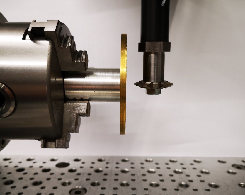
In order to cut clock wheels the first step is that I need to be able to set the cycloidal cutter centre line accurately on the centre line of the blank brass diameter. See the picture and description below.
Exaggerated mock up of the cutting setup showing a brass blank mounted on a super glue arbor and a cutter mounted in the Tormach Slitting Saw arbor. The centre line of the cycloidal cutter teeth sits on the centre line of the brass blank and cuts on the rear edge as seen above. After each cut the CNC rotary table increments the blank by one tooth ready for the next cut. (In practice the super glue arbor would need to be much larger in diameter in order to be more in keeping with the diameter of the brass blank and so ensure maximum support while the cutting was done).
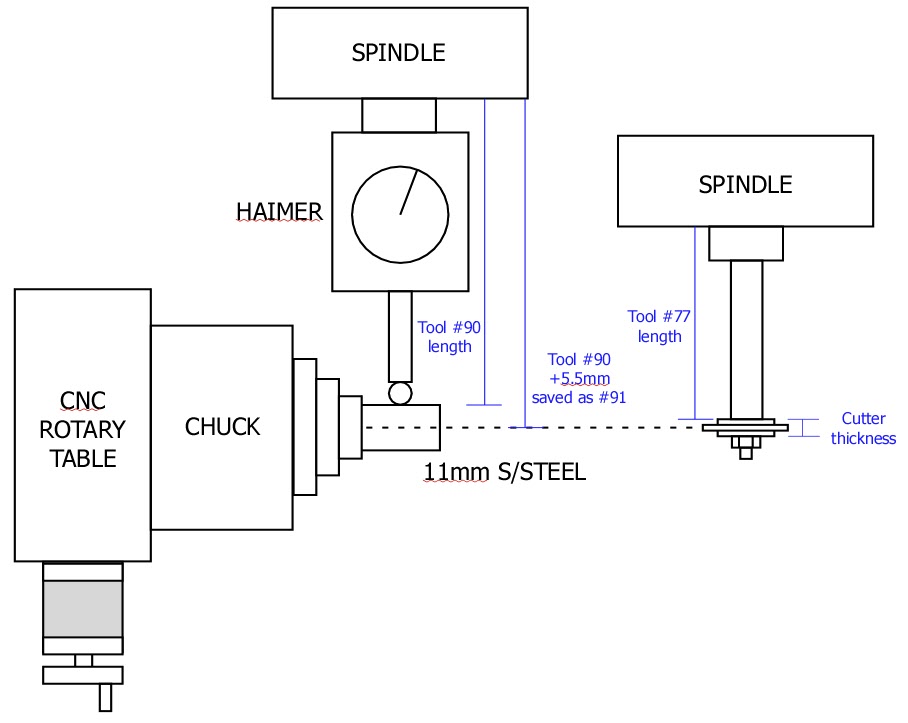
From previous posts you will know I have got the chuck securely and centrally mounted on the CNC rotary table and this assembly is in turn rigidly fixed on the tooling table. The position of the centre line of the chuck is now fixed relative to the tooling plate on the bed. The chuck and rotary table mounting bracket is sufficiently Woody over engineered to hopefully be repeatable. Likewise the distance from the spindle to the chuck can be repeatably zeroed using the Haimer and its associated tool table entry (#90).
Expanding this a little, if I put my favourite piece of 11mm diameter silver steel in the chuck and bring the Haimer down to contact it, rock the Haimer back and forth in Y to get the steel diameter peak, I can get a Z zero reading to the top of the steel. By creating a new entry in the Tormach tool table (#91) which is the Haimer length plus 5.5mm (the radius of the silver steel) I can use this virtual length stored as a new tool #91 to allow me to set the Haimer on the silver steel while actually giving me Z0 on the centre line of the chuck. So far so good.
As you might have read from an earlier post, the idea of using the Tormach Slitting Saw arbor to hold my cycloidal cutters would in theory create a repeatable tool length to the centre line of the cycloidal cutter teeth. Having this as a tool table set up in the Tormach would simplify setting the cutter centre to the centre line of the chuck and therefore the centre line of the wheel blank being cut. This is where the thinking drifted somewhat.
I created a new tool table entry (#77) that was the length of the saw arbor to the shoulder that the cycloidal cutter fastens against. I thought I could then follow the same routine as detailed above and add to this length the half thickness of the cutter and create a new tool table entry to match. This would once again create a length which would give the centre line of the cycloidal cutter.
That was fine until I measured my tray of cycloidal cutters to see what the thickness of the cutters were …… sadly consistent they are not. There seems to be no standard by manufacturer or diameter. I have cutters with thicknesses from 3mm through to 7mm. I could create a new tool table entry for each thickness but this is a recipe for a mistake when selecting the correct tool table entry for the cutter being used.
The simple solution I think is to use slitting saw arbor tool table length (#77) as the initial setting length to Z0 and then do a G0 Z-x.xx where x.xx is the half thickness of the cutter being used. Once Z has dropped to this reading the Z axis can be re-zeroed to run the wheel in question with the cutter in question now sitting on its centre line on the centre line of the chuck.
Simple diagram showing the concept of using the Tormach tool table facility to allow easy setting of the centre line of a wheel blank and cycloidal cutter centre lines
I hope that all makes sense …. I could of course just eyeball it and not try to be so fussy but when you have the tools to make things easier you might as well use them. I also need to look after my precious piece of 11mm diameter silver steel.
Each year the engineering club I am a member of has a Halloween Steaming evening for families and friends. The 7″ ground level track (1.35 miles / 2.2km) and the 5″ raised level track (1361 yards / 415m) get decorated with spooky stuff and we run with lights on the locos.
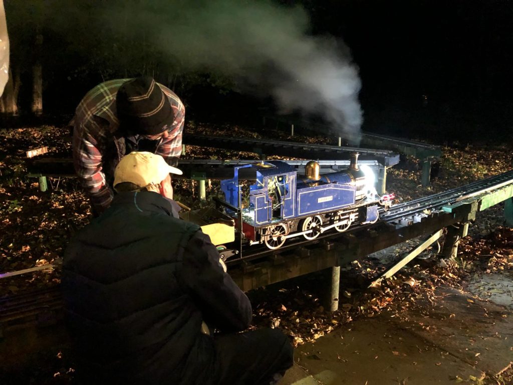
I fit a 100mm diameter angel light ring on the smoke box door and have a couple of small LED torches either side of the front running board and a red flashing rear light. The front view is pretty bright as a result but evening running in cold weather means lots of steam and seeing what is going on is difficult. Add to this I need my spectacles on to see the water level in the glass and my specs steam up. Add to this the fact that the oiler is running a bit heavy at the moment so my specs also get a fair amount of oil splatter.
I started the fire using charcoal soaked in white spirit and had steam pressure fairly quickly. I loaded the fire to just below the first line of tubes and set off.
I was pulling both my driving trolley and the passenger trolley and worst case this was 3 adults. I had severe wheel spin if I wasn’t careful with the regulator movement. The raised level rails are aluminium and the weather was damp so this was not unexpected. When heavily loaded the fire was really drawing well but as the evening went on it became more of a struggle to maintain steam pressure. The top of the fire had a crust of darker red on it but when the fire was poked this broke away to an incredibly bright fire.
Analysing this is difficult. Was the fire too deep and the draft from the Rosebud not sufficient ? Were the holes in the Rosebud getting clogged with ash and reducing the draft ? Or something as simple as letting the water level drop too low ?
Lots of questions that I am still working on. That aside I definitely need a session on the rolling road to adjust the oiler.
Picture taken by my son as myself and Dave prepared for another run.