One of my favourite additions to the workshop has been a laser centring tool for use on my Tormach PCNC milling machine. The tool consists of a low cost laser diode mounted on a 3D printed disc and with a 19mm steel shaft. The tool is held in the Tormach spindle power drawbar. The laser is angled inwards towards the spindle axis at approximately 20 degrees. The 3D print has facilities for a battery supply and ON/OFF switch such that when the laser disc is pulled into the power tool bar collet it switches on the diode.
In use, as the spindle is raised or lowered, the rotating diode creates a circle of light on the milling table which can be used to locate and centre the spindle on features of the item being machined. This might be to locate the centre of a hole or the centre of a block depending on need.
I recently had the need to use my four jaw centring chuck on my Myford lathe. Usually I duck and dive to avoid having to use the 4 jaw as I find it frustrating to set up. This recent bout of frustration lead me to wonder if I could adapt my laser centring tool for use on the lathe such that it would give me a guide ring of light to show where the material was sitting relative to chuck centre.
On the milling version the laser rotates and the job stays fixed. On a lathe version this would be similar. The chuck would be stationary and the laser would rotate in the tailstock.
I am quite anal in needing to have a tidy workshop with everything having a place where I can find it easily. It is a kind of insurance policy to perhaps give me a bit longer time in the workshop before I lose the plot altogether. (The less palatable advantage is the dealer who comes in to clear my workshop when I am in turn in ‘a box’ can easily see what a treasure trove he has stumbled on. We’ll move swiftly on from that thought).
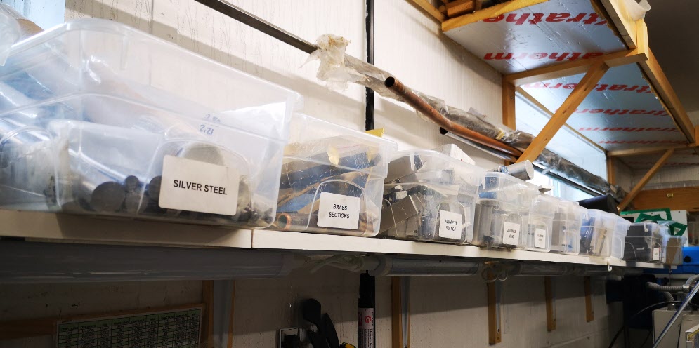
To this end I have settled on using 5 Litre Spacemaster storage boxes for all my ‘stuff’ (technical term as defined by my long suffering wife). These are readily available in the UK at Dunelm and on the net. They are made from a very durable plastic and supplied with a lid which is rarely useful for my application. I believe they are principally intended for ladies to store their shoes in.
Update : – Dunelm no longer supply Spacemaster boxes but Zoro UK have added them to their range. Their stock code is ZT1053092X.
The boxes have a 6.5″x 12″ footprint and are 4″ deep. It is surprising just how much workshop kit can be stored in these (and of course nicely labelled). The 12″ is just not long enough for 13″ silver steel but a little hang over can be tolerated for such useful material.
How sad is this ? Just a small section of my anal storage system
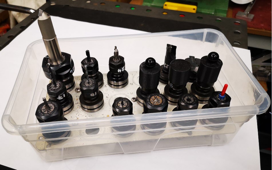
I have accumulated a reasonable (by my standard) set of Tormach TTS tooling collets with my preferred tools permanently fitted. These are each numbered to match my tool table entries in PathPilot. The numbering is done using an Edding 750 white paint marker.
My solution to storing the collets was to use the same boxes. I used a sheet of Dural (150mm x 290mm) and punched a (3 x 6) matrix of 20mm holes into it to take the collets. The Dural sheet sits on 5 off 10mm diameter x 36mm long spacers.
Spacemaster 5L box used for TTS tooling storage. Side view showing Dural plate
To give you some idea of the strength of the boxes, you can pick up one of these fully loaded with tools by the front wall and your wrist will break before the box does. (Well you know what I mean).
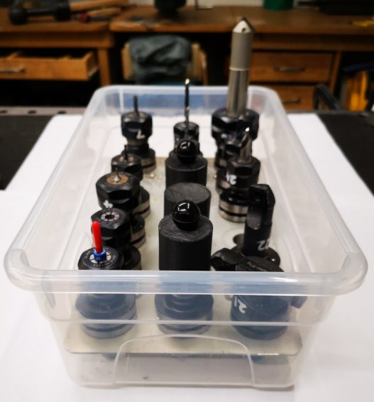
You will notice in the above photo that after some expensive clumsy breakages I now fit 3D printed caps over the most fragile tools such as carbide PCB drills.
Spacemaster based TTS storage box showing protective 3D printed caps over fragile tools
So a bit of a slow news day but thought this might stir an organisational initiative somewhere ……
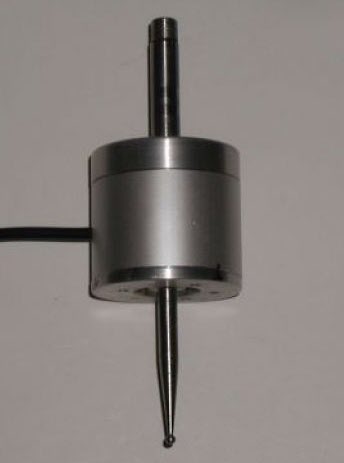
I bought one of the Wildhorse Innovations Passive Probes some time ago and it gets used occasionally (usually when I have dispatched another Haimer tip to happier hunting grounds).
The Passive Probe as supplied by Wildhorse Innovations
The Wildhorse design is nice and simple and it can be bought with a ‘Tormach Option’ which is a cable with a ready fitted 5 pin DIN that is pre-wired to plug straight into the Tormach 440 accessories socket. I have to say it did not talk to the Tormach PathPilot interface immediately. I had to snipped the pull up resistor inside the unit to solve this. When in use on the Tormach you have to designate the probe as Tool 99 in the tool table so as to be able to utilise the PathPilot probing routines (which are very good).
So where is all this going ? Well it is a A to B to C progression …
I dusted the probe off to use the other day and as I had not used it for some time, I did a centring calibration of the probe ball point while mounted in the Tormach spindle. This is a real pain to do as the three centralising adjustment screws are on the bottom face of the body. As a result you can’t see what you are doing and there is a danger of knocking your dial gauge in the process and having to start again.
This got me thinking about whether I could do this adjustment off line in the lathe. This way the adjustment screws on the bottom face are readily accessible. This seemed like a good idea except the umbilical cable is permanently wired into the unit so it needed to be protected from a disastrous wrap round the chuck. Initially I wrapped the cable around the body of the probe and held it there with masking tape but it wasn’t ideal.
Watching the probe spin in the lathe chuck made me also realise that because I had mounted the probe in a Tormach TTS collet this was a waste of a collet. It might also be adding to eccentricity through using such a combination. So you see that one thing leads to another and to another. A workshop wormhole.
A plan was made. Fit a connector on the probe body to allow the cable to be disconnected and replace the existing mounting rod with a TTS equivalent.
Finding a suitable connector was a bit more tricky than expected in that there is not a lot of room inside the probe body and a connector that protruded too far would foul the spring loaded mechanics. My search for a suitable connector combination Iead me to a 2 pin Binder rear mounted socket (Part Number 09 0074 00 02). Being pedantic it should be a fixed plug as the connecting cable connector (Part Number 99-0071-100-02) would now have two exposed pins carrying a voltage. The supplier only had the fixed socket version in stock so I conveniently looked the other way on that argument – the cable would rarely be unplugged so not likely to be a problem …
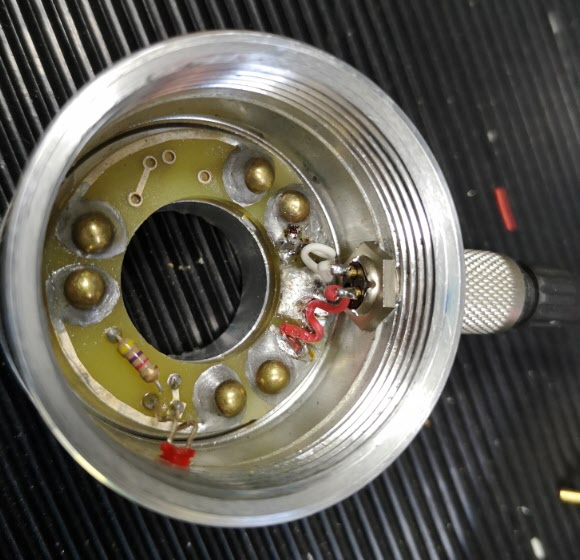
The circular body of the Wildhorse Probe is quite substantial. When the connector arrived and I was ready to proceed, I took a picture of the existing wiring and then snipped the cable clear. I enlarged the hole in the body wall to 9mm but then discovered that the mounting thread on the connector was not long enough protrude through the probe body wall far enough to pick up on the retaining nut. To overcome this I milled a flat area on the shell outer surface. The two connecting wires where then soldered in place on the fixed connector and then on the mating male connector on the free end of the cable.
Internal view of the probe after the Binder socket had been fitted
The next job was to make the new fixing rod. I always try to have 19mm silver steel available in my stock box. This matches the TTS collet outside diameter. I decided I would make a new mounting rod with the silver steel and I would increase the threaded mounting hole on the probe top to M8 from the 1/4″ size as supplied .
Top cover of the probe inside view of the M8 inside the spring retaining counterbore
The larger diameter would provide a larger shoulder on the rod to tighten against the probe top. Using M8 would allow the stud mounting hole to still sit within the pocket that retains the pressure spring. The rod was faced and turned to 8mm for 5mm or so and the M8 thread cut and undercut with a graver. The other end of the rod was faced and then a 45 degree chamfer turned on it. The finished rod screwed nicely into the top plate and the body now seemed to run solidly square to the central axis.
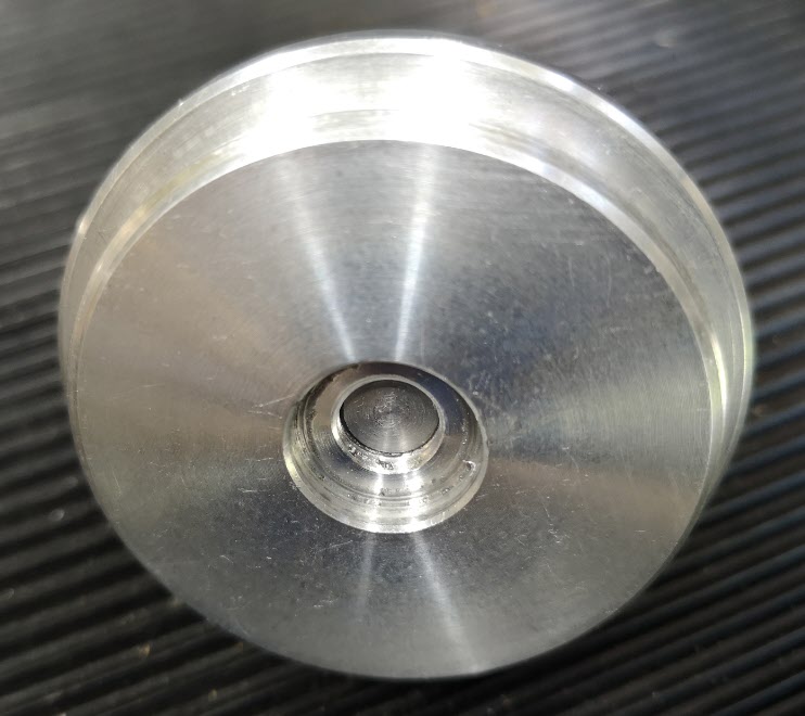
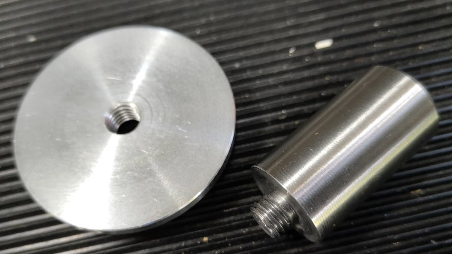
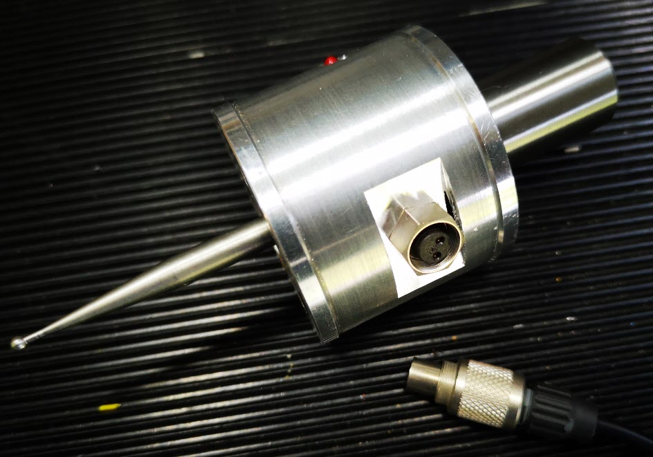
The new 19mm OD silver steel mounting rod and the outside surface of the top cover to which it is fitted.Finished modified probe showing connectors fitted with the flat milled surface and the new mounting rod.
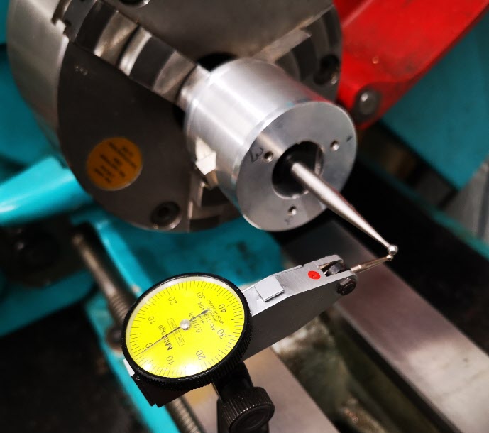
All operations were now complete and I mounted probe with its cable unplugged in the lather chuck with the new 19mm rod. I mounted my dial gauge on the lathe bed and set about centralising the probe ball. It was so much easier in the lathe with no cable to get in the way of things. Transferring the modified probe to the Tormach afterwards gave very similar centralising results.
Modified probe mounted in the lathe to allow easier access to the three centralising screws
So a typical workshop wormhole progression from job to job but as ever it was time well spent.
I am still building up to automated wheel cutting on the Tormach.
I have mounted the Sherline CNC rotary table on my tooling plate and the table now needs a chuck or collet mounting plate fitting. This will grip the super glue arbors that I use for holding the wheel blanks while cutting.
I decided a chuck would be the best option and bought in a low cost 80mm three jaw chuck made by Sanou. These are available from a number of outlets on EBay. It is supplied with internal and external jaws and a chuck key.
It arrived very quickly and felt horrible. Turning the chuck key was really gritty and jumpy. Rather than sending it back I decided it would be worthwhile stripping it down to see what was going on.
I have never attempted stripping down a chuck before and to my surprise it was relatively simple. I first removed the three jaws, then the three rear cover retaining screws, the three adjuster retaining pins and finally the three adjusters. In theory then the spiral plate should drop out. But it didn’t and it took some serious tapping with a soft tool to remove it.
Having got all the bits apart and in front of me I began to deburr all the sharp edges that I could find. What seemed particularly important was to clean up the spiral plate internal diameter as this seemed to be the tightest fit. A flat diamond coated file together with a triangular one were the best tools to use. Once all this was done I put all the parts in the ultrasonic cleaner with hot water and detergent. There was a surprising amount of grit in the bottom of the tank once cleaning was finished.
Re-assembly was the reverse with everything being coated with moly grease before assembly. It was now a completely different chuck. Beautifully smooth.
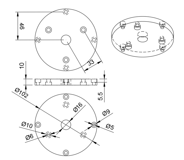
The next problem was mounting the chuck on the CNC table. I first made a mounting plate with three M6 clearance and counterbored holes on the PCD mounting holes for the chuck (66mm) and four M5 clearance and counterbored mounting holes to match the cross slots on the CNC table (96mm). I also put a 16mm clearance hole in the centre of the disc to match the chuck bore. Next problem was how to centre the chuck on the rotary table. Fortunately the rotary table has a central, tight fit 11mm (0.25″) shouldered hole leading to a UNC 3/8″-16 screw thread. This is the mounting for use on Sherline products. I cut the UNC thread on the end of a piece of 11mm silver steel and screwed this in place at the centre of the table. This was perpendicular to the table face.
I then fitted the chuck to the backing plate and lowered the chuck and plate assembly over the 11mm rod and loosely tightened the jaws. This allowed the chuck to just rotate so that the four table slots could be aligned with the four holes in the mounting plate. These four screws were also loosely tightened against the T slot nuts and then the chuck pushed firmly down and the jaws closed tightly. The four table mounting screws were then tightened. The chuck should now be centrally placed and tightly in position.
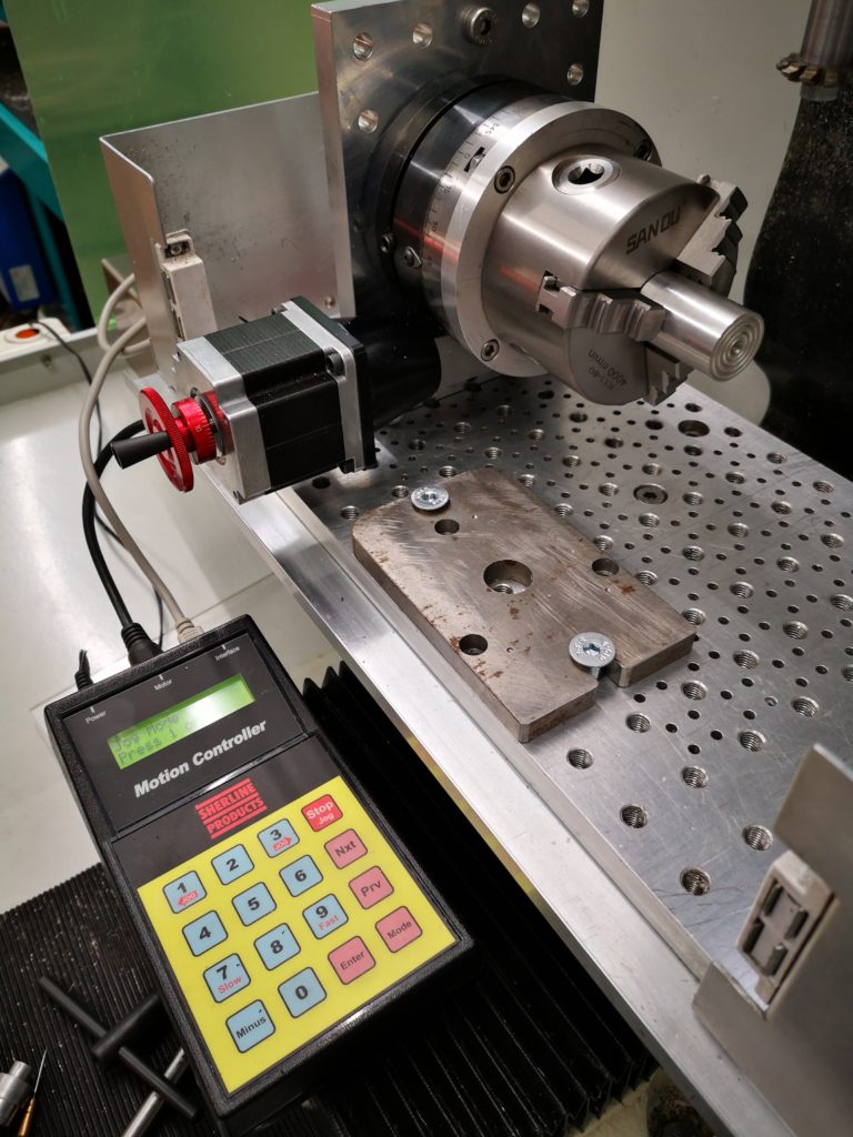
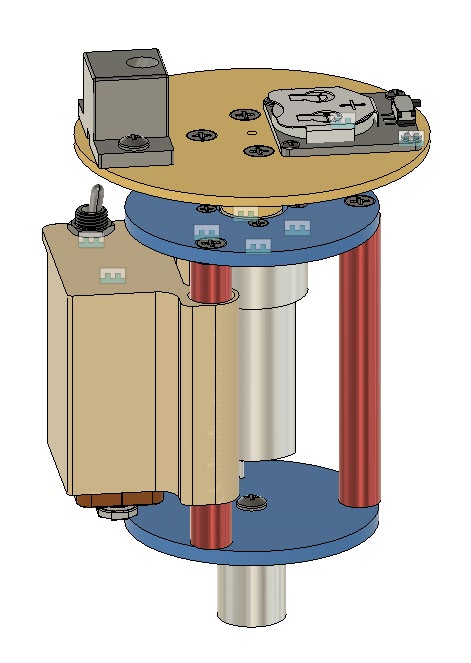
Sherline CNC table mounted on the Tormach tooling plate with the Sanou chuck on its mounting plate and with a super glue arbor in the chuck. The controller for the Sherline table is shown which was designed by Bryan Mumford who also designed the Microset Clock Timer. The weird plate on the Tormach tooling plate is a lump of scrap steel for my dial gauge magnetic base to attach to. You can just see a cutter in the Tormach slitting saw arbor at the top right.
The 11mm silver steel centralising rod could be unscrewed and removed. I put a piece of 20mm silver steel in the chuck jaws and checked the run out as being +/-0.05mm which to me didn’t seem bad and more than adequate for the task intended.
A new experience and a good end result.
Still got the GCode to sort out to automate the process … and finish off the USB expansion unit to increment the motion controller.
Update : –
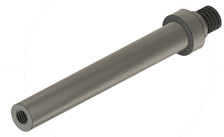
I found that just a straight 11mm rod with a 3/8″- 16 UNC thread on the end was not reliable in sitting square to the CNC table surface. This resulted in the chuck running eccentrically. I modified the centring rod to have a collar fitted (16mm diameter to clear the chuck central hole) which was silver soldered in place and then trued up on the lathe. This modification allows the chuck to be fitted and centred easily and quickly each time. Here is the Fusion 360 model.
Chuck centring rod (11mm diameter silver steel) with a 3/8″-16 UNC thread to fit into the Sherline CNC Rotary table central mounting hole and with a collar to pull up against the rotary table face to keep the rod true. The M6 hole on the rod end is for a cap head screw held in place with Loctite. This allows easy release of the rod from the rotary table once the chuck is in place.
I also added a M6 threaded hole in the end of the rod to allow the fitting of a cap head screw. This is Loctited in place and is used to release the rod from the rotary table central threaded hole once the chuck is in place. An alternative would be to mill a hex head on the end of the rod but I took the lazy way out.


 Next problem was how to centre the chuck on the rotary table. Fortunately the rotary table has a central, tight fit 11mm (0.25″) shouldered hole leading to a UNC 3/8″-16 screw thread. This is the mounting for use on Sherline products. I cut the UNC thread on the end of a piece of 11mm silver steel and screwed this in place at the centre of the table. This was perpendicular to the table face.