I had previously posted about the low cost HD microscope that I had bought to see if was any good. For the price I was impressed by the microscope but not by the stand that came with it. It only needed to be breathed on to wobble and the fixing was poor.
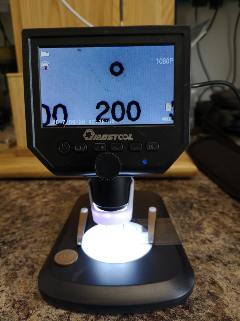
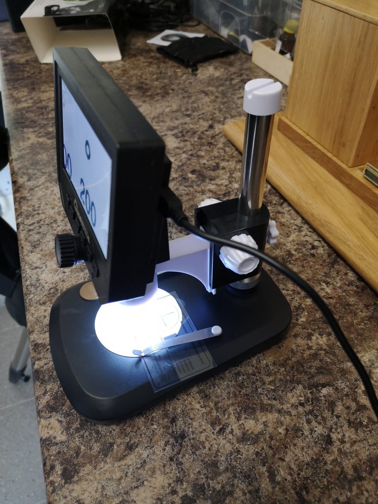
While browsing Amazon I spotted a more conventional looking stand for sale. This was sold as being aluminium but when it arrived this morning this was a bit creative being mostly plastic. However the microscope fits into the cup holder mounting and it makes a dramatic difference to the stability and therefore the usability of the microscope. You can preset the height with a knob on the rear and then there is a rack knob to move the scope up and down. You can focus using the microscope control or on the stand rack knob.
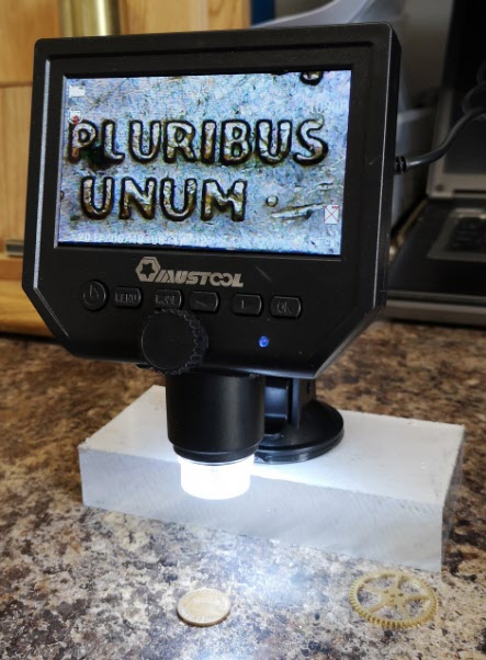
It is now a stable device to use and for the price of the microscope and the stand it is a useful addition to the tools available. The stand comes with a calibration sheet to allow you get a feel for the magnification factor. The picture below is displaying a 200um circle.
I took the engine to the club on Sunday and did around ten loops with the Rosebud Grate in place.
I made a mess of lighting the fire initially by trying to go to coal too quickly and as a result had to put the external electric blower back on. Once the fire was glowing well I migrated onto the track.
The engine pulled well but was lightly loaded with only me on my small driving trolley. The fire appeared evenly spread over the grate and there was definitely a more noisy ‘drawing’ sound. Other members who had fitted Rosebud’s to their engines commented that they find that they have to leave the steam blower on more than they had been used to when the engine is idle.
So a bit inconclusive so far and more testing needed.
Owners of Polly V locomotives suffer the frustration of juggling the original bar grate into the firebox opening and then getting the ash pan to seat correctly before inserting the retaining pin. With the old bar grate I had mounted some reference blocks on the ash pan floor to keep the fire grate roughly, but still lose, while the ash pan was juggled into the correct position and the retaining rod inserted. On a cold frosty morning at the track, when keen to get steam up, this was always a pain to do. I resolved to fix or at least ease this problem on the new Rosebud Grate.
Resolution
I have a ball bearing rolling road that fits on my B&D Workmate stand and this allows easier access to the underside of the engine.
Polly V mounted on the workmate rolling road with finished grate at the front
I mounted the new Rosebud Grate in place in the bottom of the firebox and threaded some 16 SWG wire through the firebox door and into a pair of the holes in the centre of the new Rosebud Grate. I could now pull the grate upwards and hold it in place in the firebox floor opening. I did a dry fit of the ash pan and inserted the retaining rod. Looking back down into the ash pan from the rear of the engine I could see that with the grate pulled up tightly into the firebox opening (using the wire) there was about 3mm of clearance between the ends of the new grate supporting pillars and the ash pan floor.
Leaving the grate securely in place, held with the wire, I dropped the ash pan out of the engine and cut a piece of card to exactly fit inside the ash pan bottom surface. I painted Engineers Blue on the ends of the Rosebud Grate mounting pillars. Very carefully I offered and fitted the ash pan in place and inserted the retaining rod. I then released the retaining wire on the grate and let the grate drop so that the grate pillar ends contacted the card and left blue witness marks. I tightened the restraining wire again to lift the grate and then dropped the ash pan. I had four usable blue marks on the card showing where the pillars were located relative to the ash pan base.
I drilled out just the two best marked diagonals pairs with 5.5mm holes and then dropped the grate out of the engine and mounted it on the ash pan. I cut the length of the two M5 mounting screws such as to be tight into the pillar holes while not quite gripping the ash pan floor. This gives a degree of movement (aka slop) when offering the assembly into place on the locomotive.
Magic !
Now only a single integrated lump (grate + ash pan) needs to be juggled in place on those frosty mornings.
Items used for the Rosebud Grate fitting and mounting.
Update :-
This afternoon I ran the Polly up on the rolling road with the new Rosebud grate fitted. After lighting with white spirit soaked kindling, the safety valves were blowing after 17 minutes. The fire looked bright and even on the blower and on no-load running. It is not a true test but certainly looks promising. Following the rain over the weekend, we have been given permission to run steam once again at the Club so maybe an outing is called for on Sunday to get a real feel for the changes.
I often have a look on Banggood for tooling items for the workshop but the other day a low cost microscope caught my eye. I regularly get thin slivers of brass and steel in my hands and fingers and they are a real pain to find never mind remove. I thought for the price being asked this microscope might make a low risk purchase to help my failing eyesight.
It arrived today, looked really cheap and nasty out of the box yet I am staggered by what it does. The screen is HD and there is a card slot for local storage. You can record stills or video. Have a look at the following link : –
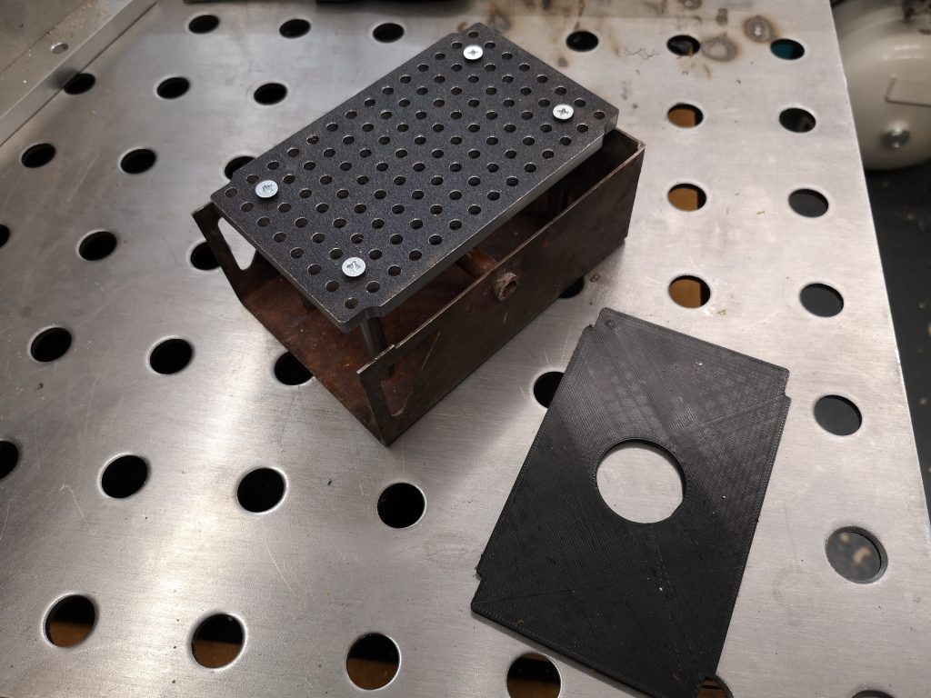
While doing the drawings for the Rosebud grate on Fusion 360 I cheated slightly. From my measurements, I made a best estimate sketch of the needed grate size to fit the firebox floor and having drawn this up, I did a 3D print of an equivalent size thin piece of PLA. Having trial fitted this printed plate I did some trimming on the Fusion drawing ready to create the CAM.
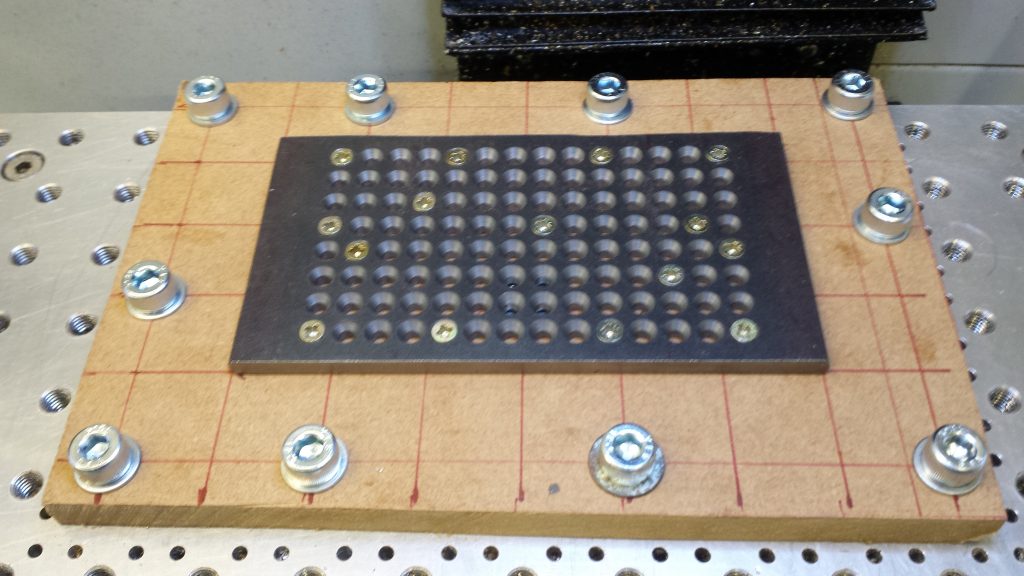
I had bought in some 150mm square black mild steel plate and cut it roughly to width but left the length at 150mm this being longer than needed. This allowed me to clamp the ends of the stock to my tooling plate on a piece of MDF. I had one clean cut edge on the cut stock to use as a reference. When mounted I checked this with the Haimer to make sure it was running parallel in the X plane. Note I cut the MDF to roughly the same size as the plate so as not to interfere with the clamping.
I did a PathPilot width and length measure using the Haimer and found the centre of the plate and set this as G54. My Fusion drawing and CAM were referenced to centre. I was now ready to go.
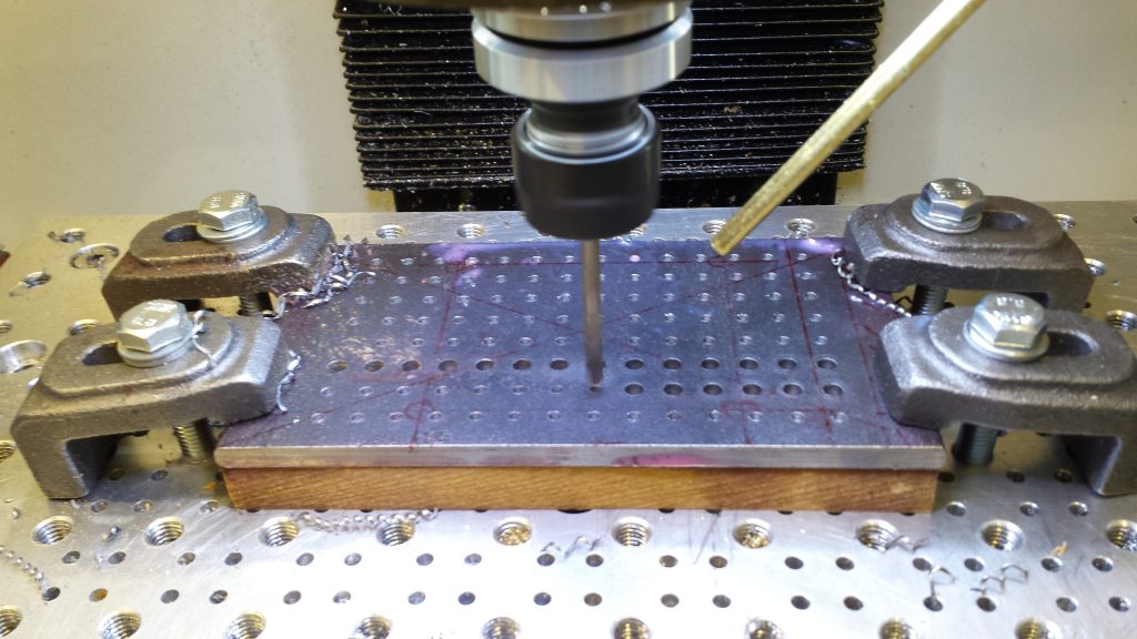
First operation was to spot the matrix of holes and the second op was to drill them out to 4.1mm. Third op was to countersink the holes to 3mm depth. This was a bit interactive. I just worked on one hole only to start with and did repeated cuts using a BS3 countersink until the depth was correct. I then did a ‘chose similar size’ selection in Fusion CAM and then ran the full op.
This now left machining of the profile of the plate to the size of the fire box floor dimensions as per the CAM and my dummy PLA plate.
First Ops on the Grate, spot drilling and then hole drilling. Note the clamps on the outside of the plate area.
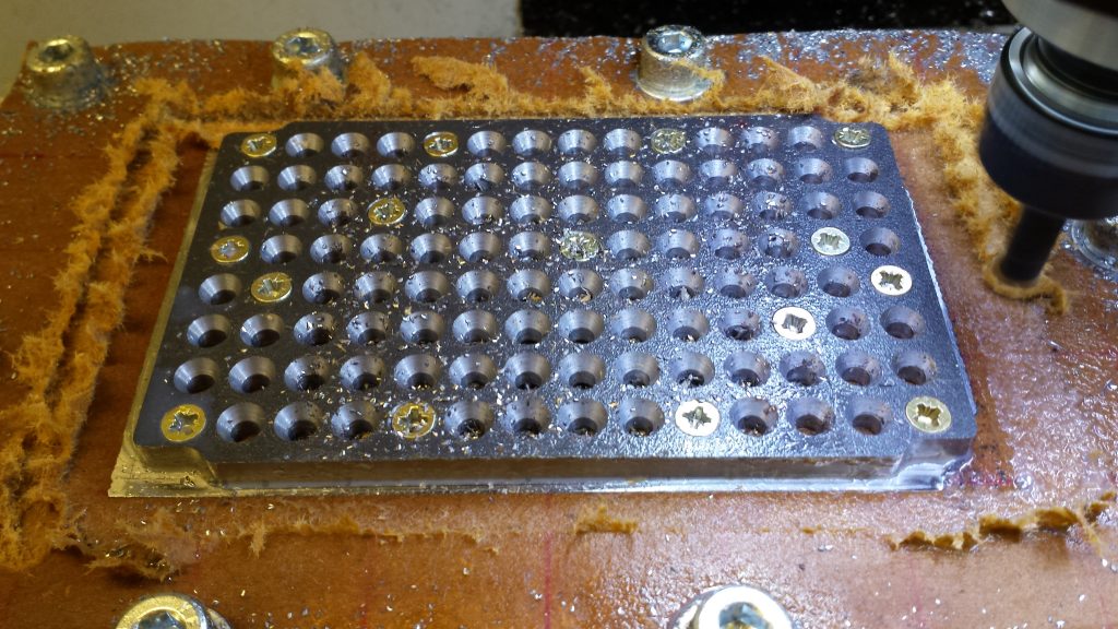
Clearly the clamps were now a problem as the end areas were excess material on the length. To get round this I removed the drilled plate from the MDF (the MDF had already started to degrade and swell with the cutting fluid) and mounted a new piece of MDF on the tooling plate with M8 fixings. As you will see below I went a bit OTT with these …. there is even a hidden countersink one under the plate to stop the MDF bowing upwards …
I remounted the grate on the new MDF with a single woodscrew in one of the grate holes and checked and adjusted the angle of the plate so the good edge was running true in X as before. I then added a ‘sprinkling’ of more wood screws so the plate was firmly in position and running true. I then re-referenced G54 to the centre of the grate as before.
Plate remounted on a new MDF backing plate and held in place with randomly placed wood screws using the grate hole matrix.
Now I hate making swarf (chips) of material if it is not necessary … so having got the plate securely in place on the MDF I then took it off again and cut off the excess material on each end of the length. Sad really but you never know when you might need a couple of small pieces of steel …
The grate could now be mounted back on the MDF with the plethora of screws positioning it back as before. I did re-check with the Haimer and also rechecked the Z height once again.
The CAM adaptive profiling was with an 8mm cutter. Obviously I was cutting air at each end of the grate where the stock was now missing but not a problem.
Profiling almost complete. The MDF is starting to degrade and swell.
I could have used a super glue and masking tape holding method but the black mild steel does not have a smooth surface like BMS and I was doubtful how well it would hold. With hindsight the method I adopted did give me some flexibility in the process method.
The final process on the Myford Super 7 was to make four posts to sit the grate at the correct height spacing above the ash pan to match the old bar grate position. These posts were fixed onto the grate by sacrificing four of the holes. This of course reduces the hole count and therefore the hole area percentage occupancy from 15.17% to 14.62% – but not worth worrying about.
Finished grate standing in the ash pan and also the 3D printed test shape
So now I have to prove that all this effort was worthwhile and the grate will make a difference to the Polly V steaming. More to follow on this in due course. We have had some rain over the past couple of days so the Club track will no doubt be open for steaming in the near future.