Gearwheel Designer Update

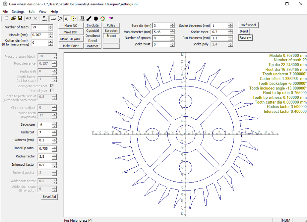
Graham Baxter has added a Brocot escape wheel design preset button in his latest version of Gearwheel designer (GWD). This additional preset function came in useful as I had a client asking whether I could copy a 22mm diameter 29 tooth Brocot wheel from a French clock. The wheel was damaged with missing tooth and two further teeth which were bent .

I had never before attempted cutting a wheel this small and fragile looking but it might be a good learning experience so I stuck my neck out and said ‘yes I can do that’ before I had actually seen how delicate the wheel would be.

I measured one tooth under the microscope and then used Fusion to create a circular array. The update to GWD allowed me to make a second version. Here is a screen shot of the model.

Using GWD in this respect needs some additional comments.

GWD will let you create the 2D geometry of the wheel and from this create a DXF. You can also create a direct CNC code to cut the wheel or a STL version. It is a very powerful piece of software.

My normal route is to export the DXF from GWD into Fusion using the Fusion’s Insert menu. Once in Fusion I can then extrude the 2D design to the required thickness and create the manufacturing GCode in Fusion. A qualifier is needed on this. If you are running the Fusion hobby licence you cannot import a DXF into Fusion. This is a real pain for hobbyist users.

If your intention is to create a 3D printed version of the GWD wheel then you can create a STL export and import this directly into your slicer without going via the Fusion route. With this direct route you need to set the Z depth in GWD. The Z depth value is the thickness of the wheel (equivalent to the extrusion value if you had gone the Fusion route). Note that in GWD the Z value is always a negative value. So if you want your 3D printed wheel to be 3mm thick you enter -3 in the Z offset box.

The next bit is a bit weird. When you import the STL created by GWD into your slicer it will appear as just the edges of the wheel outline with no infill. If you then run the slicing routine the infill appears correctly and you are good to go on a print. (I have tried this direct STL route and via the DXF Fusion route and the model in the slicer is exactly the same).

Back to the Brocot wheel …

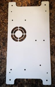
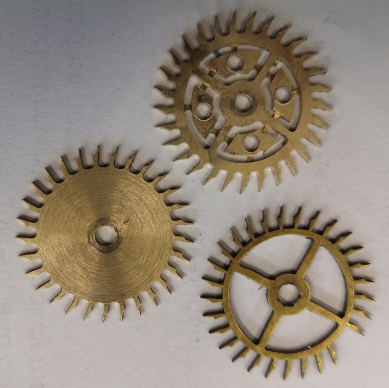
Both versions were cut on my Tormach 440 CNC machine with the CAM created in Fusion. I used a Blue Builders tape superglue fixture to hold the stock in place. Here is a picture of the result.

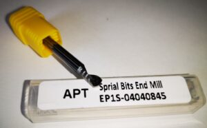
The left hand wheel is the microscope measured version before the petals were cut. The upper one is the GWD version with the petals cut but retained in place by breakout tabs. The lower one is the original. Machining was done with a 1mm diameter end mill at 10,000 rpm.

The client chose to install the fully finished GWD version and the clock is now running happily once again.

There is a full write up of my process in the February 2026 edition of the Horological Journal. This is the monthly magazine of the British Horological Institute.

Links to similar or related post are listed below : –

MX3660 as used on Tormach PCNC440

My Tormach PCNC440 made a nasty electrical bang the other day. At first I believed the 48V main power supply had died but it was simply being dragged down by a fault in the Leadshine MX3660 master stepper controller.

As ever the Tormach helpline was supportive and helped with the diagnosis. The replacement MX3660 was likely to be a long delivery delay from the States. It would probably have a significant delivered cost after shipping and VAT were added to Tormach’s ex works price.

Some checking on the web revealed a company called Motion Control Products which was listing the MX3660 but their URL was a dot com address so at first I assumed that they were also Stateside. After looking closer I discovered they were located in Bournemouth UK, around one hour from my home. Although they listed the MX3660 as a line item they were not showing stock. A request for deliver leadtime to their sales team brought an answer from Richard in Sales to say he had found one in stock. Happy days.

A few days later the new MX3660 arrived. After setting the DIP switches to match those on the fried one, I installed it and switched on. My Tormach burst into life and the cover plates could be fastened back in place.

The obvious moral to the story is don’t blindly assume a dot com can’t be a UK supplier…..

Links to similar or related post are listed below : –

Tormach Power Drawbar piston service

For some time my compressor has been intermittently kicking in without anything running to justify it. By chance I heard a slight hiss and then felt a small ‘breeze’ coming from the bottom of the Tormach drawbar compression cylinder stack. This device has three pistons stacked together to give enough downward pressure to open the drawbar gripping the TTS collet. The machine was installed in 2016 so the seals have done quite well to survive this long.

I did some web based research and found that Tormach offer a seal replacement kit so clearly this was something that was an expected service activity. I ordered the kit (which cost less than the courier charge). Here is an image of the kit.

My research also found a very old YouTube post by John Saunders at NYC CNC where he describes how to undertake the service activity. It looked like a job I could manage.

My PCNC440 model was slightly different to John’s in so far as removing the piston assembly out of the machine. On mine you have to just remove a single shoulder bolt and a pull out pin. However before doing this you need to put any of your TTS tools in the collet to relieve the pressure from the cylinder plunger head. Once this is done, turn off and bleed the air supply before removing the two air feeds. Mark them so you know which one goes to which port. Also mark the three piston sections with a Sharpie so you know which order and orientation they are in.

The piston stack has the three sections clamped together with four bolts inserted from the top of the stack. The bottom end mounting plate also has long screws that pass through spacer tubes but only fasten into the bottom piston section. Note that these spacer tubes might well have some large additional height setting washers so don’t lose them.

I suggest removing the bottom three screws first of all so you are left with just the three cylinders still held together by the top four bolts.

Now for a tricky part – you need to remove the large circlips that are fitted to the top and bottom ends of the piston stack. These are not easy to remove unless you have a decent tool to grip them. Basic handheld circlip pliers are unlikely to perform and you could end up search the workshop for flying circlips. For this reason you must wear some eye protection while removing the circlips. I bought in a pair of these pliers and they were superb for the job.

Once the circlips are removed you can remove the four top bolts holding the stack together and be able to split the three sections. Be careful how you do this so you see and understand what is where and the order of assembly.

The end plates that were held by the circlips are pushed outwards. All the other sections should freely slide out as appropriate.

With everything ready, start from one end of the assembly and do a logical swap out of the old seal and swap in the new one and re-assemble that section. Clean off any debris in the seal grooves and add new grease to the seals and their locating grooves. I used silicon grease.

The kit comes with 6 standard section O rings, 3 wider section rings and 3 central piston seals as shown in the image above. By swapping only one seal in and out at any one time you get a good control check that you haven’t missed anything.

My kit also had some small O rings that are not shown in the Tormach image of the kit contents. I can only assume that the kit is universal to a number of other piston types.

Update : Tormach has since confirmed that the extra small O rings are for the 770 and 1100 versions only.

The whole swap out activity took around 2 hours. This piston worked fine when re-installed back on the 440. “Phew!”

Editing irregular PCB shapes in FlatCam

How to create irregular outline cut paths and board cut outs

Following a request from a subscriber I have edited my FlatCam tutorial document to include a section on how to profile irregular board layouts and boards with cut out areas. The attached ZIP file contains the new version of the write up and a short video clip showing the board outline editing process.

Links to similar or related post are listed below : –

Experiences CNC machining Aluminium Composite Material (ACM)

I had a recent request to machine some panels in 3mm thick ACM.   This has a polyethylene core sandwiched and bonded between two thin sheets of aluminium.   The sizes of the various panels requested could not be easily accommodated on my Tormach PCNC440 CNC mill so I had to dust off my CNCEST 3040T baby router.   Five out of the six panels would fit inside the 3040 working footprint but the sixth required me to revert to a two setup movement of the workpiece in the Y axis.  My write up of this stepping process for oversize objects can be read here.

The CNCEST 3040 has a maximum spindle speed of 10k RPM and is controlled using Mach3 with all the frustrations that brings to the party plus manual tool changes etc etc.

I received DXF drawings of the panels and these were imported into Fusion where they were simply extruded to 3mm before processing in Fusion Manufacturing.  Each CAM operation was exported as a separate function into Mach3 regardless of tool changes.  This gave me step by step control.

I used a 12mm thick MDF sacrificial (spoil) backing board to mount the panels.  As all the panels were of the same general dimensions this made mounting the panels a repeatable process using a fixed matrix of woodscrews into the MDF.  The 12mm depth of the mounting board made the tooling pin reference holes for the Y move much more rigidly fixed and as a result more repeatable to use.

The main problem encountered was that the ACM does not readily adapt to machining with conventional end mill cutters.   I tried using my stock 2 flute parts and these would skim on the top aluminium surface while the plastic underneath deformed to the Z axis increasing pressure.   Once sufficient pressure was exerted the tool would finally bite into the aluminium and punch through into the plastic with a noticeable ‘clunk’.  This played all sorts of havoc with the Z axis height referencing and also lead at one stage to the Z axis stepper coupling working lose.

The solution was to go to a single flute spiral cutter style. These were purchased from APT Tools (UK supplier).  Hot knife through butter comes to mind with the result of this change.

Single flute spiral end mill from APT Tooling UK
The single flute spiral end mill from APT Tooling UK

For straightforward hole cutting I used standard PCB carbide drill bits from Drill Services (UK supplier).  These are nice to use as all have a standard 1/8″ shank which makes tool changing a little bit easier.

Once all these frustrations were overcome the process became much more repeatable albeit with one or two curved balls due to Mach3 lock ups.  Have you ever enjoyed trying to manually re-reference a half finished job ? …..

The finished largest panel that required a two step movement in Y axis

More accumulated knowledge gained and lots of black plastic swarf (chips) to clean up before it could migrate everywhere into the house.

Similar or related subjects : –

Verified by ExactMetrics