Simple Dual Pulse Arduino Based Generator

I have a current project on the go for a clock synchroniser. This takes two pulses, one from a GPS reference source and one from a secondary variable source and calculates the time difference between them to correct the clock. The system is Arduino based and I needed to be able to test my software logic without having to manually initiate the two pulses. The result is this simple but very useful pulse generator.

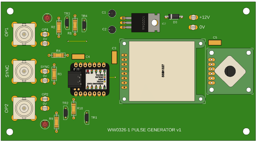
The generator is based on my favourite Xiao SAMD21, a SSD1327 OLED display and an Adafruit rotary encoder. The PCB layout was designed in the Fusion Electronic module and uses through hole components. There are only two top side links so it is easy to mill the artwork using the Fusion manufacturing data in association with FlatCAM. Production boards will be run via PCBWay.

The software provides two output signals that can individually have their rep rate and pulse width defined via the OLED screen and the rotary encode. The two streams can be independent or locked together. If locked together then a delta phase shift can be programmed in. Here is the working unit built onto the CNC milled PCB. The enclosure is a simple 3D printed trough.

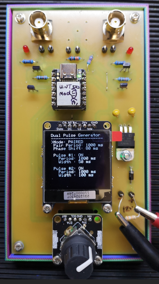
The missing BNC placement is a possible external sync input enhancement ( a rainy day job …). The unit is powered from an external source with a 5V on board regulator to feed the logic. There is a 3V3 to 5V buffer driving each pulse output (two digital transistors, two resistors and a LED indicator).

This development had been put on hold. Using a discrete rotary encoder I could not get a stable response on the OLED display and there was poor interaction with the encoder – lots of jitter and missed steps. The Adafruit module uses the same encoder but mounted on a small pcb that has an I2C encoder built in. The SSD1327 has the option for a SPI bus and an I2C interface. The new configuration using the combination of the encoder on I2C and the OLED on SPI completely cured the all earlier problems I was having.

Let me know if you would like a production PCB.

Links to similar or related post are listed below : –

It’s Horology but not as we know it Jim

If you visit any car boot sale / brocante /yard sale you will almost certainly come across old mechanical clocks that probably have a wonderful history if they could only speak.  Their previously loving owners have ‘passed on’ and the inheriting family probably don’t like the looks of the timepiece or just can’t be bothered to wind it up or it simply no longer works which is a big problem with a rapidly diminishing fraternity that know how to fix them.

Now what follows is going to disturb the purists so they should look away.

When I find a specimen that has some character or aspect that appeals to me and has no historic value I will offer the few coins being asked and give the clock a new life.  Not by repairing them in the true sense but by fitting a modern time code based radio locked mechanism.   Here in Europe we have DCF in Germany and MSF in the UK. DCF in particular has an astonishing geographic range for its signal.

The time code locked mechanisms are available from a number of sources and vary from a basic straightforward hours minutes seconds mechanism to ones with higher torque and some with a pendulum.   The pendulum is quite independent of the time keeping but does add character. As supplied the radio locked mechanisms require you to set the hands to either 12 o’clock if you are on European time or 11 o’clock if on GMT and then you pull out a locking pin on the rear of the mechanism and install an AA battery.   The mechanism will twitch momentarily and then the hands will start to rotate from the setting position to a set hour position and then hold until the mechanism gets an update from the radio signal.  Once locked to the radio signal the clock will be very very accurate.   You can check them against time.is and as would be expected they are spot on.  When clocks need to be seasonally change the mechanism  automatically updates.  When the battery dies you simply put a new one in and the clock resets itself to time.

I have modified many clocks in this way and gifted quite a few to friends and family.   I try wherever possible to retain the original hands and sometimes this involves a little lathe work to modify the mounting bosses.

There are two examples below including my latest find, an ex British Air Ministry office clock dated on the back as 1951.  I am quite pleased with how this one has cleaned up and it is now heading to France to hang in my workshop out there.

So next time you see an unloved traditional mechanical clock gathering dust give some thought to giving it a new lease of life.

dcf clock mechanism in traditional clock
1951 Air Ministry clock modified for DCF radio control
rear view of dcf clock mechanism in traditional clock
Rear view of ex Air Ministry clock showing new DCF radio controlled movement
example of DCF mechanism in a traditional clock case
Modified clock with DCF radio linked clock module

  Similar or related subjects : –

Verified by ExactMetrics