Decision made on the new 3D printer but it’s big
As per the previous post I have been debating long and hard about which new 3D printer to buy. Strangely enough my wife gave me a hard time about my indecision and told me to just to get on with it.
Qidi sell into the UK market via Amazon and having placed an order, a very large box arrived very quickly onto the doorstep. Very large. But also very well packaged with very good unpacking instructions. It did take the two of us to lift it into position on the bench. Which was the second problem – where to put it. The temporary position is on the side of my desk but this might change.
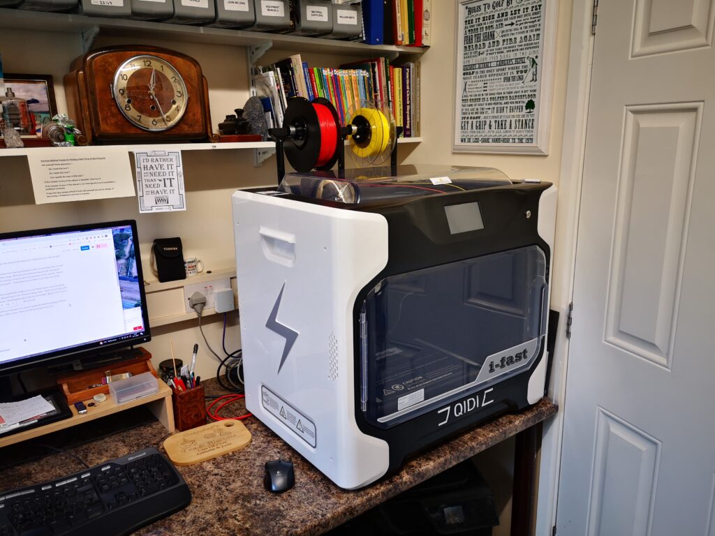
The I-Fast has a dual extruder and you get both a high and a low temperature extruder head which are easily swapped out depending on the filament being used. Print size is huge being close to a 300mm (1 foot) cubic space. Two filament dry boxes are provided to keep moisture out of the filament (although I haven’t used these yet). Qidi provide a print slicer which looks a lot like Cura and so far seems fine to use. There was no problem in linking the export from Fusion 360 directly to the I-Fast.
I’ve run some test prints and find it fast and very quiet compared with my old Sindoh DP200 (which is currently sat sulking in the corner). More to follow as I get used to it.
Links to similar or related post are listed below : –
- Hybrid 3D brass threaded insert tool
- Tap shank adapter for 4mm AF hex drivers
- Qidi Slicer auto support error on my part
- Qidi X Smart 3 revised fan installation
- Qidi X Smart 3 tweaks
- Qidi X Smart 3 special weekend pricing
- Stop losing Qidi ifast 3D prints down the chamber front gap
- Fitting a Bento air filter to a Qidi ifast 3D printer
- 3D Printed Brass Threaded Insert Soldering Iron Stand
- eSUN filament reel silica drying pod