Changing the Drive Belt on a Cowells ME90 Lathe
One of the posters that Jimmy Diresta sells says “I’d rather have it and not need it than need it and not have it”. The saying is apt and often strikes home. This is not just in terms of larger workshop assets but also in the small scheme of things like workshop tooling. You know the time you spent making a jig for a job and thought ‘all that extra time and effort to just make that and what do I do with the tooling now ?’
I think it is a saying that is close to the heart of many hobbyist no matter what the medium you are working in. It does explain why our workshops are full of ‘stuff’ that we accumulate on the ‘just in case’ basis. How many screwdrivers do we really need ? The answer of course is ‘one more’.
I believe there should be a sub clause to Jimmy’s poster – “Needing it and Having it yet not being able to Use It”.
I have a Cowells ME90 mini lathe which is a beautiful piece of engineering and I seem to remember it was my first real mechanical engineering purchase. For 364 days of the year it sits looking forlorn at the back of the bench asking to be valued, loved and used. When it is called into use it is indispensable. Usually. On a recent once in a blue moon 365th day when it and only it could perform a task for me I found the drive belt to the headstock had perished. You could almost see the grin on the ME90s face. Gottcha mate, serves you right for not looking after me.
Thankfully the drive belts are standard sewing machine belts (#MB410) and are readily available both direct from Cowells or numerous sources on the Internet including Amazon. A replacement was ordered and it arrived quite quickly.
Now to the nub of the problem – how to fit the belt ? Looking at the headstock it suggested that maybe the whole assembly had to be lifted off and split but the cap head screws for this which went down into the baseplate did not want to budge. I looked at the spindle and it seemed to have differing diameters that at first glance would not allow it to be removed out of the bearing mounts.
Rather than risk a regretful step I emailed Cowells and very quickly got a support reply from Colin. For all future intrepid belt changers here are his instructions : –
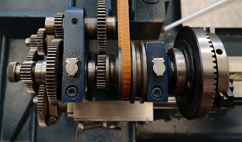
The only way to fit the belt between the 3 step pulleys is to dismantle the headstock assembly.

Its quite simple really:-

Start at the left hand side of the headstock.

1, Unscrew the knurled gear retaining nut.

2, Pull off the 20 tooth gear ( be careful not to lose the tiny Woodruffe key beneath it).

3, Unscrew the round adjuster nut that butts against the large (64t) gear. -You can use a pair of pliers/grips if you put some emery cloth in their jaws.

4, Slacken the M5 grub screw ( or take it out) in the 64t gear.

5, Pull this gear off. (If it is reluctant to budge then, its probably due to a burr underneath- see below for advice).

6, Slacken the M4 grub screw( or remove) in the little collar that abuts the headstock pulley inside the headstock channel.

7, Slacken (or remove) the grub screw in the central vee of the headstock pulley.

8, Slacken the tension on the two bearing adjuster journals- these are the large cap head screws you see on the top face of the headstock body.

9, It should now be possible for the headstock spindle to eject toward the tailstock.

Clean all parts thoroughly and re-assemble in reverse.


If you have trouble removing the 64t gear then, make sure all grub screws are removed as above. Screw back on the knurled gear retaining nut and with a hide mallet, gently tap the headstock spindle toward the tailstock.
As I said in my thank you reply to Colin, I felt like a hybrid version of ‘stupid boy Pike’ and ‘Rodney you plonker’. (UK sitcom specific joke).
Enough said ?
Similar or related subjects : –
- Error Code A9 on Odealis Gas Boiler
- Power banks that go to sleep with low current drain
- GyroCut versatile scalpel replacement
- Dry lining wall fastener fixing aid
- Simple Vice tommy bar modification
- Soldering Iron bit storage on Lytool soldering station
- Water Softener goes AWOL
- Noga External Deburrer and Cut Screws
- Technoline Wireless Weather Station problem
- Using Raaco section boxes for fastener storage

 With hindsight the large pulley could be 3D printed by leaving the rear face completely flat rather than having a profile like the front face.