Tormach Post Processor G53 Edits for Tool Change

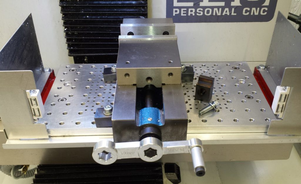
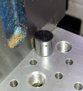
The Tormach PCNC440 is a lovely machine and is more than big enough for my present needs.   The one problem I had encountered was when coming to a tool change on a CNC job sometimes there was not enough Z height to get the TTS collet out of the spindle.   This was particularly difficult when using larger diameter drill bits in a chuck style holder.

Once in program there did not seem to be any option to break the run and do a G30 or similar.   What I really needed was a move of the spindle upwards and outwards to get it clear of the job and allow TTS access.

Reading up in Peter Smid’s excellent CNC Programming Handbook I could see that care was going to be needed to ensure that any movement was first of all a Z action and then X and Y to avoid the danger of crashing the tool into the job or its fixtures.

I had some discussion with John Saunders at NYC CNC and John was working on a video around this subject.  He helped enormously.

The end result is to use G53 machine coordinates to first do a Z and then and X and Y to move the tool up and to the side for tool change access.

This involves edits to the post processor in three places.   The first two edits (Lines 44 and 66) are there to give an option for this movement in the drop down selection box.  (The line 24 edit is an earlier modification to allow Mill Turning – see separate post).

tormach, post processor, G53
Line 24, 44, 66 edits
g53 tool change edit to post processor
Change that appears in the Property selection box where the Custom Tool Change option now appears

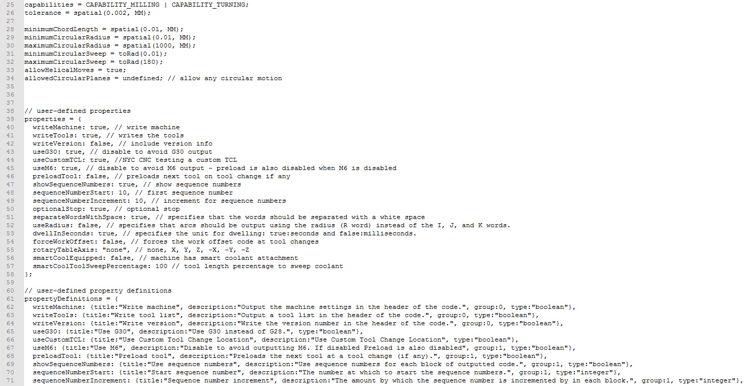
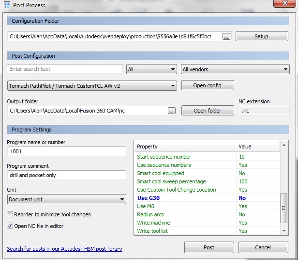
The third edit gives the instructions for this as a G53 Z move than a X and Y move (Lines 543-538).   Note that I later found that I had to add a G54 after the G53 movements as some CAM actions did not include a G54 as part of a tool change.

custom tool change edit
Line 534 to 538 edits

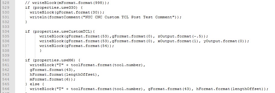
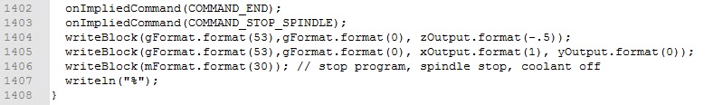
I later on decided it would be nice to include this G53 movement at program end so this is a fourth edit (Lines 1404 – 1405) and not forgetting the change for Mill Turning edit (Line 25) there are five changes in total.

cnc g53 tool change edit
Line 1404 to 1405 edits

That concludes the changes.   I recommend that you spend time watching John’s videos on Post Processor edits on NYC CNC.

If you can’t read the edits then drop me an email and I can send you a full listing.

Note that these are changes to the Tormach standard post processor code and if you are tempted to do this you should do a ‘Save As’ on the original code and only edit the newly created and saved file so you have a fall back position.  Likewise I accept no responsibility in documenting this and putting you up to potential mischief messing with your machine and causing damage.

Similar or related subjects : –

You say Vise and I say Vice but we agree that Clamps are Clamps

When I put together the package of items that I would be ordering with the Tormach PCNC440 I probably made a mistake.   I wanted a machine vice (vise if you over the Atlantic) and the recommended size for the 440 was a 4″.  However a jaw set was not available with this size the same as it was with the 5″.   After checking with Tormach I ordered the 5″ in the belief that it would be usable.

The 5″ is serious lump of metal  and really only fits on the 440 table long ways on.  The jaw set is really nice however.   Sad to say that none of it has been used so far and if I am honest it is unlikely to be used.   A large and heavy white elephant sits in the corner of the workshop.  It is going to cost more to freight it back to swap out than is economic.   Offers gratefully received !

What to do ?   Looking around I found that Arc Eurotrade offer a range of machine vices.   In particular I liked the look of the SG Iron Milling Vices as they have flexible jaw positions and had a ‘pull down’ action of the jaws on closing.  They do not offer soft jaws but at a pinch these could be made as and when needed.   I ordered a 100mm (4″) version and it is a nice piece of kit, seems solid, but not as heavy as the 5″ Tormach.

The vice did not come with any useful fixing clamps so what to do ?  I had already made a tooling plate for the 440 table that has M8 holes on a 25mm matrix.   The plate also has additional 4mm tooling pin holes within the XY limits of the spindle movement.   The vice sits nicely between the M8 mounting holes and just needed some simple ‘L’ clamps to hold it down.

Designing and making the Clamps

I designed something suitable on Fusion and did a 3D print of a prototype on the Sindoh 3DWOX to do a trial fit.   This seemed to work fine so production of four metal ones was now needed.

Fusion 360 drawing of the clamping block

A debate now ensued.  Options at this point were : –

Use the Fusion model to CNC/CAM repeat produce four individual clamps which would need three set ups to face and cut.

Use Fusion to extend the model to have four clamps in one piece of stock to be cut to length as needed but machined using a full CNC program of all four on one piece of stock.  Each clamp would still need facing after cutting

Use the single clamp already drawn in Fusion and use WCS increments to hop along the stock and create four separate clamps for cutting off as needed.  Still would need facing after cutting.

Finally given their simplicity there was the option to run them on the Myford manual mill ….

Outcome

Well my hand goes up to say I funked it and made all four on the manual mill.   I cut four pieces of stock (24mm x 19mm) to 40mm on the Kennedy hacksaw and faced the ends to length on the Myford mill.  I jigged the Y position while sitting on parallels in the machine vice before cutting the clamping step on each.  Next came an 8mm hole central in the slot before mill extending it out 2mm either side.  Job done.

Would it have been faster on CNC ?  I don’t really know.   If I had drawn the ‘four in one bar’ version I think it would as there would have been only one setup apart from the facing off.   If I had done the WCS based version of a single clamp then four set ups would have been needed, one for each WCS plus the facing.   Either way both of CNC options would have increased my knowledge on CNC and I could have chalked another ‘result’ on the 440 fuselage mission tally board.

No excuses I know, but there is just something about manual milling and the intimacy of being in touch with the metal ……

The finished clamping blocks were made to suffer heat and then an oil dunking to blacken them off to make them look almost professional.

Tooling Clamp for milling table
Vise Tooling Clamp
Vise in place showing clamps and tooling pins
vice, vise, tormach pcnc440
Wide view of vise in place on 440 table. Note the NYC CNC training course handle finding a home.

So all of that was a bit of a ramble but you get the gist – CNC or manual.

Placement Tooling Pins

In closing the last thing I made was a couple of top hat tooling pins that sit in the tooling plate and align the vice position.   This ensures the vice clamps can sit symmetrically either side of the vice.  It makes for a quick set up if the vice has been off table.  Note in the picture below the small piece of shim to get the alignment correct.  (Lazy man syndrome creeping in again).

So the shop is now ready and better prepared to cut metal.   Note also the NYC CNC training course produced vice handle being pressed into service on the new vice.  Thanks to Kevin & John for that – was it nearly a year ago ???

Similar or related subjects : –

A Parallels Rack in Fusion and Sindoh with free Spagetti

Some time ago I made a rough and ready wall mounting rack for my parallels so they would sit to hand adjacent to the Myford manual milling machine.   I used double sided printed circuit board for the construction and while not elegant it worked OK …. until after I had finished it when I found two of the set lurking in a box with a half finished job.   I had not allowed for them in the construction and being OCD me, it annoyed me to have two lose ones that did not fit in the grand order of things.

An idle half day lead to a Fusion design to replace the tired old PCB disaster.  This lead to some thinking on how to design it.   I wanted a rack that sat on the tooling board with the parallels stacked on it with a slight upward angle to keep them in place.   I chose therefore to draw it slightly strangely with the ‘back’ at an angle and extruded it accordingly.   See below.


All well and good you might say.  Less messing with angles etc.

I squirted the job into the Sindoh 3D driver software and then tried to be clever and print it with the backside down on the printer bed …. or at least what I thought was the backside down.   You will no doubt spot that that this is not a simple rotation of 90 degrees but I didn’t.

The printer began producing spaghetti that was not bonding to the printer bed.  After three re-tries I took a closer look at my design and realised that the only part of the job that was in contact with the bed was the leading edge (red arrow below).  The rest was airborne at an angle all due to the way I had chosen to draw the object and rotate it.

Reset brain and reset printing so it would be now vertical.   All was good and my nice new rack sits on the tooling board.

A little bit more brain engagement next time perhaps ?

Similar or related subjects : –

French Tablecloths and Fusion 360

OK this is a silly one I know but follows on from my theme of just how valuable a 3D printer is to own and how it makes you think outside of the conventional box when solving simple problems.

French markets always have a stall selling brightly coloured table clothes in various materials.   These rarely have a prepared hole in them for your sun umbrella to slot through as you sit quaffing and nibbling in the sunshine.   If they already have a hole it usually doubles the price.   If you make a hole yourself then it will fray and degrade.

Up steps “Fusion Man” and in five minutes you have a design for a locating boss and ring to sandwich protect the hole in the material and keep the cloth fixed on the table.   Design done and its off to the Sindoh 3DWOX to print it.

Lay the table cloth on the table where it will be used and ensure it sits square all round.   Crawl under the table and with a Sharpie pen or similar, draw the shape of the hole on the back of the table cloth.

Remove the cloth from the table and flip it over.  Place the printed ring over the marked circle and remark the circle position to the ring ID.  Cut out the marked ring circle but make the cut about 3 or 4 mm smaller all round.  (Nail scissors are ideal for cutting curves).  Test fit the boss. Because the hole in the cloth is slightly smaller than the boss diameter, the material will naturally turn up the vertical face of the boss.  Check it is not causing wrinkles in the cloth when on the table.

Put hot glue around the boss at the horizontal/vertical interface and then push the boss through the cloth to let the glue hold it in place.

Apply glue to the locating ring and push this in place over the boss to sandwich the material between the ring and the boss.  Here is a greatly exaggerated cross section.

Job done.   Siesta time.

Similar or related subjects : –

Mill Turning on the Tormach PCNC440

I just dared to hit run on my first attempt at Mill Turning.  I need to qualify this in that the first run I was cutting air above the set up.   It looked OK so I put the real material in the spindle and I got a turned part as designed in Fusion 360.   I didn’t part it off and you can see the result below.

Mill Turning set up for first trial run

Mill Turning is where you place the material you want to shape (usually a rod of some kind) in the mill spindle instead of a milling tool.   The tools are mounted on the milling table (see above in the vice) and are completely stationary but move via the actions of the table in the X axis and the spindle in Z.   The software is conned into thinking the material is really a milling tool and that the tools are the material.

It has taken me the best part of a week to work out how to model this in Fusion 360 and I have been helped enormously by watching Jason Hughes on YouTube.  It involves allocating a different Work Coordinate for the location of each tool.

If I can get this more streamlined and get some better lathe tooling in place to support it, then I will be able to turn clock pillars.   This was the last stumbling block in moving to CNC assisted clockmaking.

Tonight I am a very happy bunny.  A glass or two of Merlot with dinner perhaps ?

Update – For a full write up on the process and how I got there go to my mill turning page and download the pdf.

Similar or related subjects : –

Verified by ExactMetrics