Probes and Haimer Taster Modification

I have been using a Wildhorse Innovation CNC set up probe for some time now.  It works OK but sometimes the results are not consistent.   After one frustration session I decided to upgrade it to the Hallmark ITTP probe from Threadexpress in New Zealand.  

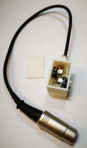
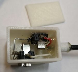
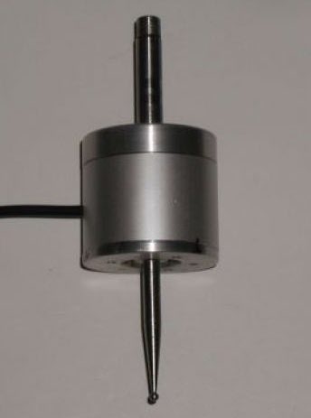
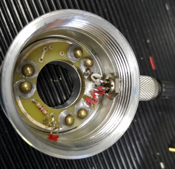
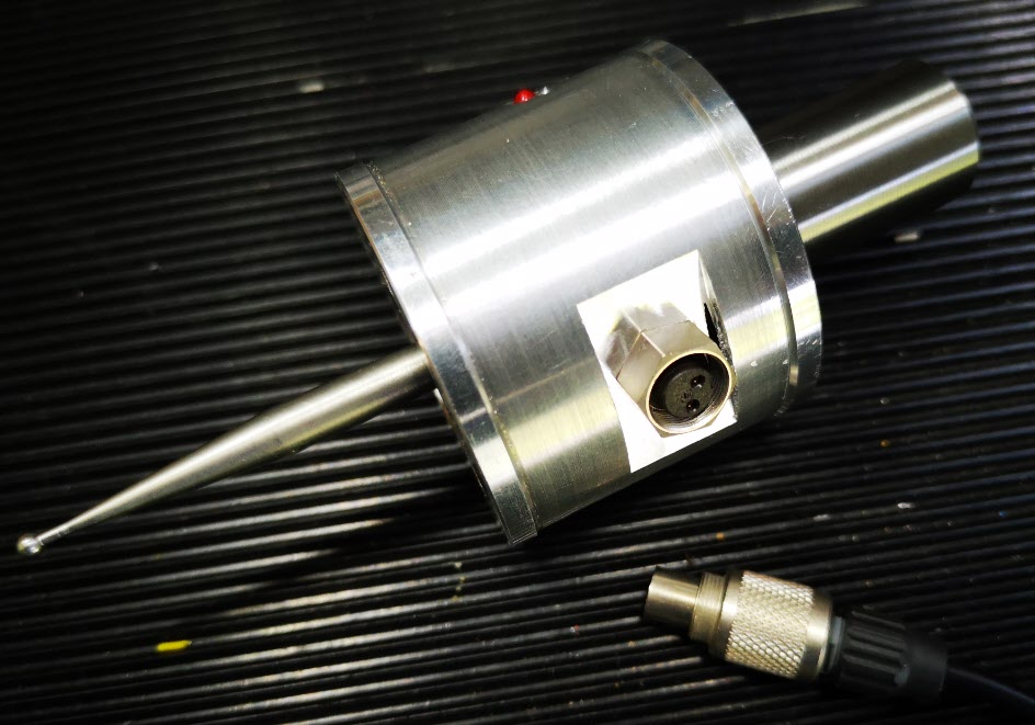
It arrived today after nearly a month in transit due to the current lock down restrictions.  On opening the package I was impressed with the quality of the engineering.  It is a nice device.  It uses the usual 3 pronged contact mechanism.   Supplied with the probe is a tube of grease that helps protect the contact reliability.  The interface cable has a 5 pin DIN that plugs into the Tormach expansion socket and the shank is a standard TTS compatible size.

hallmark ittp cnc probe mounted on the tormach pcnc440
The Hallmark ITTP probe mounted in the Tormach ready for setup and testing.  You can also see my angel ring light illuminator and Hall Effect tool height setter.

I ran through the initial preparatory procedure and then loaded it into the Tormach 440 spindle.   Pathpilot has a number of excellent set up routines to adjust the probe and make measurements.  One of these, the Effective Tip Diameter is quite critical.  All this went to plan and very quickly.  Some initial probing gave repeatable and accurate results so first impressions are good.  

Some of the Tormach PathPilot CNC probing routines
PathPilot probe setup screen and the two probing routine screens.

I’ll give some updates as the probe gets pressed into service but my first impressions are good with repeatable accurate readings.  

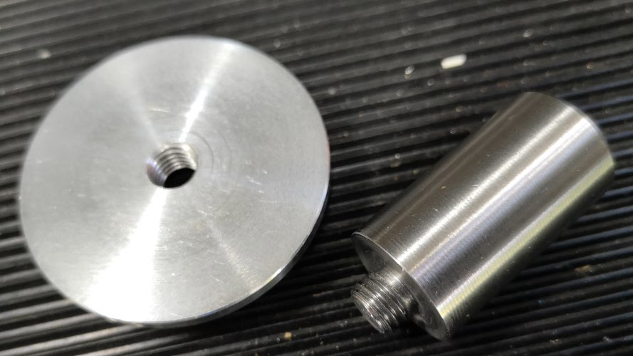
In the course of checking out the ITTP probe I needed a reference cross check on the various setup measurements.   My Haimer Taster seemed a bit erratic and on inspection I discovered the axial shank holding bolt had worked lose.  This meant a re-calibration of the eccentricity of the probe point would be needed.  

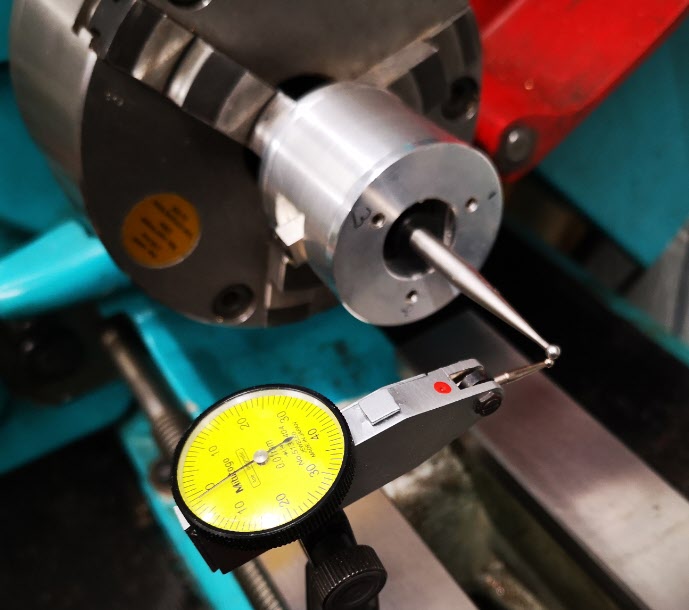
The alignment process involves adjustment of four grub screws in the shank body.  These tweak the ’tilt’ of the shank to get a concentric rotation of the probe ball point.   As there are four screws I use two hex Allen keys to make the adjustments to each in line pair.  This is quicker than with a single hex key being swapped from side to side.  It is a bit like the process I use when centring a 4 jaw chuck. The adjustment is done against a dial gauge riding against the probe ball point.   Once you get the knack this process doesn’t usually take too long using the two key method.   

The frustration is that the Allen keys provided with the Haimer are a bit chocolate based and the ends chew up easily.  The result is you tighten a grub screw and the hex key end twists and gets jammed into the hex socket in the grub screw.   While trying to waggle the jammed key you mess up your carefully made adjustment.  Aaaargh !

I ground back the worn end of the Allen keys to clean up the hex profile but they quickly degraded.   In the end I took the grub screws out completely and replaced them with some M4 cap head bolts.   Joyful !

adjusting screw change on Haimer Taster concentricity adjustment
How ugly is this ? Replacement screws on my Haimer Taster

Yes I know it doesn’t look pretty but it is now a real pleasure to make the adjustments with a couple of larger T wrenches.  It is probably a criminal thing to do to such a lovely instrument but life is too short.

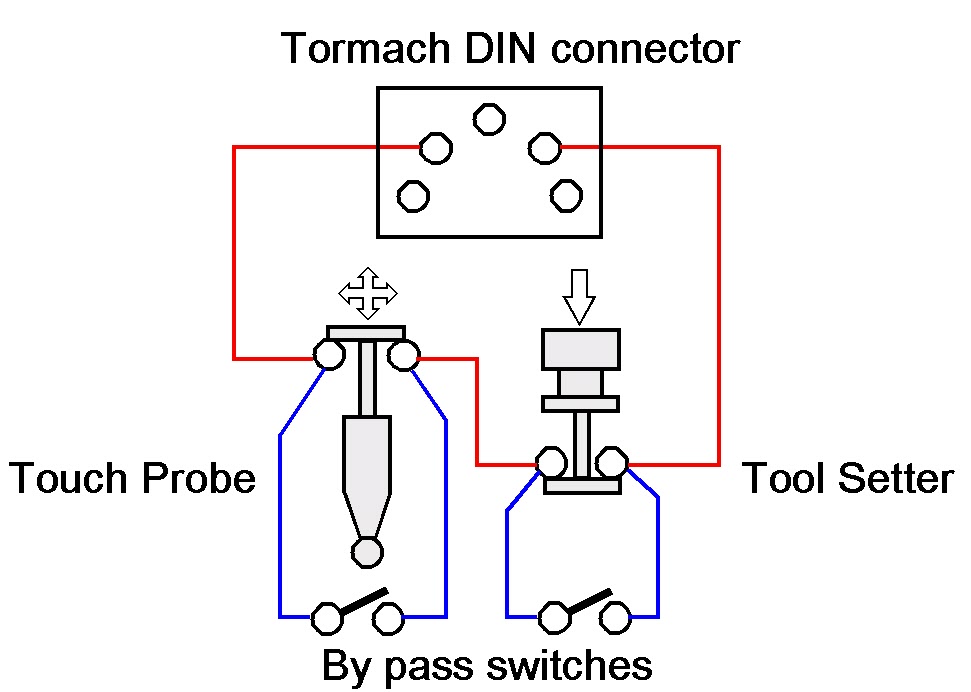
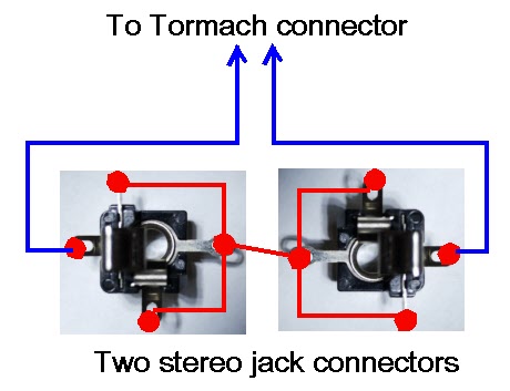
Next job will be to modify the arrangement of my tool sharing junction box on the Tormach expansion port so my Hall Effect tool height setter and the ITTP can share the input.

Similar or related subjects : –

Tormach PathPilot G37 Update

I have my Tormach PCNC440 wired into the workshop network and as a result if a new version of PathPilot is issued my PathPilot controller warns me.   This is quite nice as there is no formal emailing warnings of new issues by Tormach.  Anyone whose machine is not Internet connected would need to check periodically with the Tormach site to see if an update was needed.

To continue the story … last week I got a warning of a new version of PathPilot (2.4.0) was available and I duly downloaded.  One of the immediately obvious changes in the new firmware was a G37 tool measurement routine which works in conjunction with a simple Normally Closed tool setter.   From my previous ramblings you will see that I had done a combiner box to allow both probing and toolsetting to share a common input to the Tormach.   In theory I was therefore ready to go ….

From my many years in industry I should know that all that glitters etc … the new routine did not work.   I thought it must be me but in the end I logged a support call with Tormach and sent them my log file.   I also logged the problem on the NYC CNC forum to see if anyone else was having the same issue.   I did get one response saying that he was not having an issue.   The plot thickened and nothing back from Tormach.

A couple of days later the same responder said there was a fix update available from the Tormach site.   It seems the software worked well in G20 Imperial mode but not in G21 Metric mode.   He was running Imperial and I was trying to run in Metric   Software update downloaded and all is well.   It is rather nice.   You tell PathPilot where the tool setter is located and then to run the auto tool measurement you put a G37 command in the GCode after a tool change.   Away the spindle goes to the tool setter location, dunks the tool and updates the Tool Table.   Magic.

Still waiting for Tormach to close off my enquiry and let me know they had fixed the problem and as a result there was a new firmware available.  But it is Christmas and maybe they had other pressing matters.

Similar or related subjects : –

Probe and Toolsetter together on Tormach PCNC440

New Tool Setter Arrives

I recently bought a special offer price tool height setter from Banggood.   On arrival this seemed nicely made and robust and looked like a worthy addition to the armoury.   

The Tormach PathPilot control software has facilities for tool height setting using such a probe.   I also have a Wildhorse Innovations probing tool for edge and centre setting.   Both these devices can be connected to the Tormach PCNC440 external input accessories connector which is  a 5 pin 180 degree DIN.

The input to the Tormach accessory socket is a 2 wire connection.   Sensing and operation of external tools like the probe and tool setter depends on the device having a normally closed connection that goes open circuit when activated (i.e. the probe tip moved or the tool setter pushed down).   The probes are in essence a single pole normally closed switch.

Frustration Sets In

After spending time having to keep swapping these two devices in and out of the accessory connector I figured there must be a better way.

The Tormach does not care if you connect multiple probes at the same time provided they are all in series on an electrical loop to and from the two pins on the interface connector.   Any device when activated will break the loop and create an interrupt to the PathPilot software.   Because you will be in the area of PathPilot software that relates to the function you are measuring, the relevant probe will be the one you are intending to use.

The Solution

What was needed was a simple interface box that allowed the two probes to be connected in electrical series back to the two pins on the DIN connector.   I also wanted flexibility to be able to unplug either of the two probes and not affect the operation of the other.   This meant that on removal of either probe it would need an electrical short circuit across the pins of the connector from which the tool had been removed.

This could be done with a small by-pass switch, that is normally open circuit, connected across the connector.  You would manually close this switch if the probe is removed. 

This is fine so long as you remember to activate the switch when you remove the probe otherwise the sensing loop will see an open circuit and the software will get confused.

My solution was to use sockets for the connections that would automatically provide a short across their contacts when their mating plug is removed.   A good example is an audio style jack plug socket.   These come in various sizes (2.5mm, 3.5mm, 1/4″ etc).  Usually on these sockets the tip of the connector gets shorted to another contact when there is no mating plug in place.

I had some 3.5mm stereo jack plug and sockets to hand (either mono or stereo can be used as it is only a two wire connection) and these were simple to wire for this application.   

wiring two jack sockets for the probes on a tormach

I also ran a modified version of one of my standard 3D printed enclosures to mount them in and fitted a flying lead to a 5 pin DIN to plug into the Tormach interface.   A hot glued magnet onto the bottom of the enclosure allowed flexible mounting of the box somewhere on the Tormach body.  The only fiddly bit was replacing the existing connectors on the two probes with a 3.5mm jack plug.  (Don’t forget to the put the connector shell on the cable before you solder the wires in place ….. ).

finished dual probe input assembly

close up showing the wiring on the two jack sockets

A neat solution and the problem solved.   Both devices plug into the box to perform their various probing functions into PathPilot.  Unplug one of the probes and its mating socket will automatically short out the probe connections when the plug is removed.  The remaining probe plugged into the other socket will continue to function.

Similar or related subjects : –

Wildhorse Innovations Passive Probe

I bought one of the Wildhorse Innovations Passive Probes some time ago and it gets used occasionally (usually when I have dispatched another Haimer tip to happier hunting grounds).

wildhorse innovations passive probe
The Passive Probe as supplied by Wildhorse Innovations

The Wildhorse design is nice and simple and it can be bought with a ‘Tormach Option’ which is a cable with a ready fitted 5 pin DIN that is pre-wired to plug straight into the Tormach 440 accessories socket.   I have to say it did not talk to the Tormach PathPilot interface immediately.  I had to snipped the pull up resistor inside the unit to solve this.  When in use on the Tormach you have to designate the probe as Tool 99 in the tool table so as to be able to utilise the PathPilot probing routines (which are very good).

So where is all this going ?  Well it is a A to B to C progression …

I dusted the probe off to use the other day and as I had not used it for some time, I did a centring calibration of the probe ball point while mounted  in the Tormach spindle.   This is a real pain to do as the three centralising adjustment screws are on the bottom face of the body.  As a result you can’t see what you are doing and there is a danger of knocking your dial gauge in the process and having to start again.

This got me thinking about whether I could do this adjustment off line in the lathe.  This way the adjustment screws on the bottom face are readily accessible.   This seemed like a good idea except the umbilical cable is permanently wired into the unit so it needed to be protected from a disastrous wrap round the chuck.  Initially I wrapped the cable around the body of the probe and held it there with masking tape but it wasn’t ideal.

Watching the probe spin in the lathe chuck made me also realise that because I had mounted the probe in a Tormach TTS collet this was a waste of a collet. It might also be adding to eccentricity through using such a combination. So you see that one thing leads to another and to another.   A workshop wormhole.

A plan was made.  Fit a connector on the probe body to allow the cable to be disconnected and replace the existing mounting rod with a TTS equivalent.

Finding a suitable connector was a bit more tricky than expected in that there is not a lot of room inside the probe body and a connector that protruded too far would foul the spring loaded mechanics.   My search for a suitable connector combination Iead me to a 2 pin Binder rear mounted socket (Part Number 09 0074 00 02).  Being pedantic it should be a fixed plug as the connecting cable connector (Part Number 99-0071-100-02) would now have two exposed pins carrying a voltage.   The supplier only had the fixed socket version in stock so I conveniently looked the other way on that argument – the cable would rarely be unplugged so not likely to be a problem …

The circular body of the Wildhorse Probe is quite substantial.  When the connector arrived and I was ready to proceed, I took a picture of the existing wiring and then snipped the cable clear.  I enlarged the hole in the body wall to 9mm but then discovered that the mounting thread on the connector was not long enough protrude through the probe body wall far enough to pick up on the retaining nut.   To overcome this I milled a flat area on the shell outer surface.  The two connecting wires where then soldered in place on the fixed connector and then on the mating male connector on the free end of the cable.

wildhorse innovations passive probe internal view
Internal view of the probe after the Binder socket had been fitted

The next job was to make the new fixing rod.   I always try to have 19mm silver steel available in my stock box.  This matches the TTS collet outside diameter.  I decided I would make a new mounting rod with the silver steel and I would increase the threaded mounting hole on the probe top to M8 from the 1/4″ size as supplied .

wildhorse innovations probe top with new M8 mounting
Top cover of the probe inside view of the M8 inside the spring retaining counterbore

The larger diameter would provide a larger shoulder on the rod to tighten against the probe top. Using M8  would allow the stud mounting hole to still sit within the pocket that retains the pressure spring.   The rod was faced and turned to 8mm for 5mm or so and the M8 thread cut and undercut with a graver.   The other end of the rod was faced and then a 45 degree chamfer turned on it. The finished rod screwed nicely into the top plate and the body now seemed to run solidly square to the central axis.

Wildhorse innovations probe new mounting rod and body top cover
The new 19mm OD silver steel mounting rod and the outside surface of the top cover to which it is fitted.
Modified Wildhorse passive probe
Finished modified probe showing connectors fitted with the flat milled surface and the new mounting rod.

All operations were now complete and I mounted probe with its cable unplugged in the lather chuck with the new 19mm rod.  I mounted my dial gauge on the lathe bed and set about centralising the probe ball.  It was so much easier in the lathe with no cable to get in the way of things. Transferring the modified probe to the Tormach afterwards gave very similar centralising results.

Centralising the modified Wildhorse Innovations passive probe
Modified probe mounted in the lathe to allow easier access to the three centralising screws

So a typical workshop wormhole progression from job to job but as ever it was time well spent.

Similar or related subjects : –

Verified by ExactMetrics