

Better late than never
Four weeks ago I had an argument with my wood chopping axe. . While chopping wood against a wobbly tree stump, the stump wobbled and the axe came down on my thumb end. I didn’t feel it but it took off the tip of the bone and the severed end was only hanging on by a very thin section. My wife got me to the local A&E and a very nice paramedic cleaned and strapped things together. Since then life has been fairly miserable as I battle with buttons and being unable to do much in the workshop.
The wound is now less tender and the size of the bandage is getting less bulky. I have been warned it could take months to get any sense of feel in the tip. The problem I most stuggle with is trying to ‘unsee’ the flash back image of my thumb with its end hanging off.
In the course of recounting the incident to her golfing friends my wife was told of the Kindling Cracker. This is a wood chopping gizzmo invented in New Zealand by a young lady as a school science project . There are various YouTube videos of this device on their website. It reverses the chopping process and has the axe blade stationary with the wood being impalled in it and bashed with a club hammer. A protective ring keeps flesh away from the sharp bits.
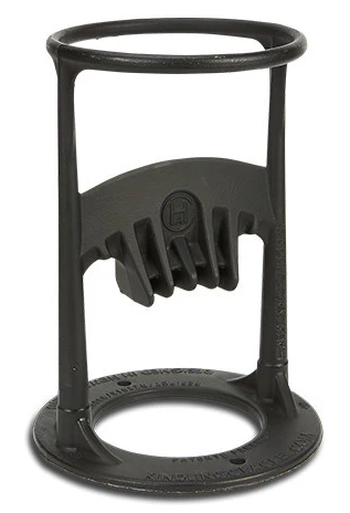
As I have been out of action in the wood chopping department, we bought a Kindling Chopper and my wife has taken over wood chopping responsibilities. She can now split wood like a check shirted lumberjack. It is a simple but elegant design. I agree it is not as quick as chopping by hand but it needs much less effort and the chore can be delegated safely to other members of the family.
The only problem is I discovered it four weeks too late and I have got a few months left to dwell on my stupidity.
Links to similar or related post are listed below : –
- Small handheld vacuum cleaner
- Eccentric Engineering Turnado freehand turning tool
- Rotring 300 2mm clutch pencil modification
- Kindling Cracker – a safer option
- SINO SDS2MS DRO repair
- A useful Amazon sourced small item storage system
- 3D Printed Threads Modelled in Fusion 360
- Three axis stepper controller PCB in stock
- Myford Super 7 Large Bore depth stop
- Tangential Lathe Toolholder for Myford Super 7


