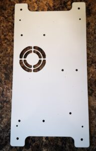
I had a recent request to machine some panels in 3mm thick ACM. This has a polyethylene core sandwiched and bonded between two thin sheets of aluminium. The sizes of the various panels requested could not be easily accommodated on my Tormach PCNC440 CNC mill so I had to dust off my CNCEST 3040T baby router. Five out of the six panels would fit inside the 3040 working footprint but the sixth required me to revert to a two setup movement of the workpiece in the Y axis. My write up of this stepping process for oversize objects can be read here.
The CNCEST 3040 has a maximum spindle speed of 10k RPM and is controlled using Mach3 with all the frustrations that brings to the party plus manual tool changes etc etc.
I received DXF drawings of the panels and these were imported into Fusion where they were simply extruded to 3mm before processing in Fusion Manufacturing. Each CAM operation was exported as a separate function into Mach3 regardless of tool changes. This gave me step by step control.
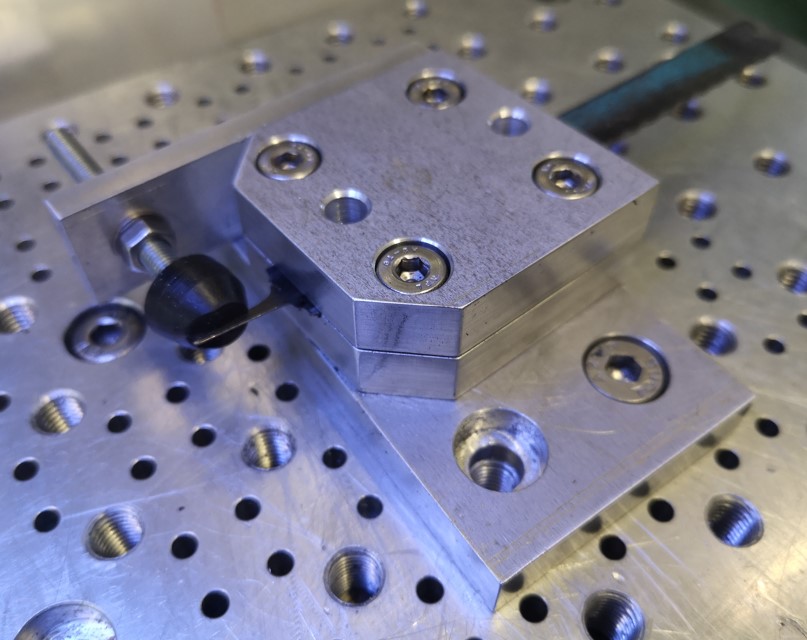
I used a 12mm thick MDF sacrificial (spoil) backing board to mount the panels. As all the panels were of the same general dimensions this made mounting the panels a repeatable process using a fixed matrix of woodscrews into the MDF. The 12mm depth of the mounting board made the tooling pin reference holes for the Y move much more rigidly fixed and as a result more repeatable to use.
The main problem encountered was that the ACM does not readily adapt to machining with conventional end mill cutters. I tried using my stock 2 flute parts and these would skim on the top aluminium surface while the plastic underneath deformed to the Z axis increasing pressure. Once sufficient pressure was exerted the tool would finally bite into the aluminium and punch through into the plastic with a noticeable ‘clunk’. This played all sorts of havoc with the Z axis height referencing and also lead at one stage to the Z axis stepper coupling working lose.
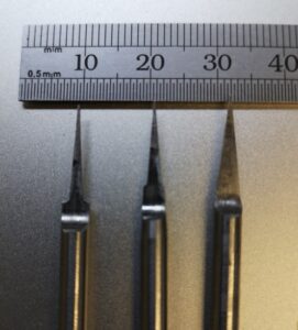
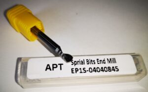
The solution was to go to a single flute spiral cutter style. These were purchased from APT Tools (UK supplier). Hot knife through butter comes to mind with the result of this change.
For straightforward hole cutting I used standard PCB carbide drill bits from Drill Services (UK supplier). These are nice to use as all have a standard 1/8″ shank which makes tool changing a little bit easier.
Once all these frustrations were overcome the process became much more repeatable albeit with one or two curved balls due to Mach3 lock ups. Have you ever enjoyed trying to manually re-reference a half finished job ? …..
More accumulated knowledge gained and lots of black plastic swarf (chips) to clean up before it could migrate everywhere into the house.
Similar or related subjects : –
- Notepad ++ for GCode Editing
- Local power USB switching circuit
- Tormach PCNC440 X Axis limit switch repair
- Experiences CNC machining Aluminium Composite Material (ACM)
- Enclosure finally added to my Tormach PCNC440
- CNC Work Reference Centring using Mushrooms
- Clough42 Electronic Leadscrew Project Implementation Notes
- Floating pressure foot for the CNCEST3040T mini milling machine
- Probes and Haimer Taster Modification
- Arc and Circle I and J code calculator for GCode cutting paths