This is the final offering … well, for the time being ….
I have been slowly evolving my ideas for fume filtering when using the Qidi X-Smart 3 printer. I should say there is nothing majorly wrong with the fan system as shipped but there always seems to be background residual fumes even when printing PLA. The level of fumes does seem to be dependent on the brand of PLA used.
The rear fan as shipped has no HEPA filtering, it simply vents the chamber into the external air. This fan only comes on during the printing process.
I have previously posted some early ideas for improving this using readily available HEPA filters. Following some discussion with Christian, a fellow X Smart user, we worked together to evolve this further.
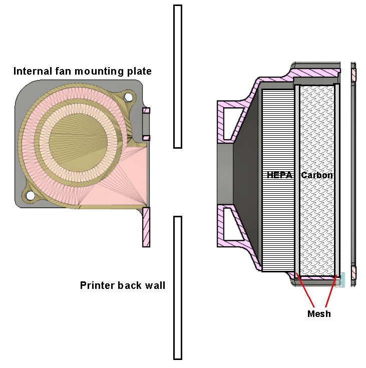
The first phase was to upgrade my external fan filter duct design to have both HEPA and a carbon granule filter sections. The carbon granules are sandwiched between two 10 gauge stainless steel meshes and an outer cover holds everything in place.
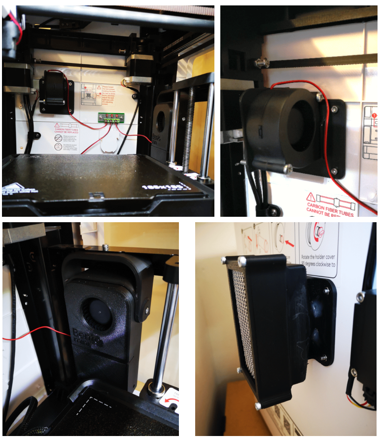
The result of this looked promising but the axial fan as shipped lacked a decent air flow through the filter stack. This was upgraded to a 6028 centrifugal fan mounted on an adapter plate. The Fusion 360 assembly is shown below.
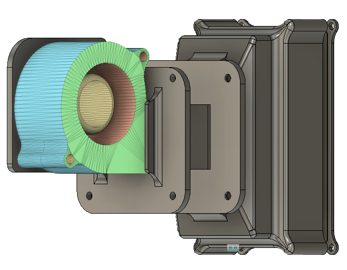
Below is a simplified cross section view. The internal fan adapter plate flange and the external filter stack are bolted together through the back wall of the printer using the original fan mounting holes and M3 screws and nuts. The fan is mounted on the adapter plate using M4 screws and nuts. There are moulded nut cavities to make assembly easier. The cover plate which holds the two meshes and carbon granules in place uses M3 screws into 3D modelled threads in the corner holes.
As previously posted I had fitted a full size Bento filter to my Qidi ifast. Further discussion with Christian revealed he had fitted the Bento Mini to his X Smart and seemed impressed by the internal air scrubbing action. I looked at the design of the Mini and after some thought changed the carbon cavity filtering walls from a printed grid to using the same 10 gauge stainless steel mesh as used above. The Bento Mini printed well and I was impressed by the thought that had been put into the design. There is a version with a hanging bracket designed for the X Smart 3.
I now had a belt and braces solution – the Bento for internal scrubbing and the HEPA/Carbon filter pod on the rear extract fan. Here are some images of all the components in place and the small terminal strip to interconnect the 24V supply.
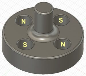
The fans used on both assemblies are the same dual bearing 6028 models as detailed in the Bento write up. These are rated at 24V @ 80mA. The axial fan originally fitted was rated at 130mA. I removed the original fan and wired the Bento and the extract fan in parallel and connected this to the original supply feed from the control board via a small terminal strip. The two fans are only commanded ON during printing.
That is my hopefully my last solution but as ever it will depend on actual performance to see whether I notice the difference in air quality. Mission creep is always possible.
As mentioned in a previous post, I designed some booster feet to fit over the existing feet on the printer. These increase the air gap below the printer to allow more air flow. If you print them in TPU they gave extra stability to the printer and reduce resonances.
Here is a link to the STL files and write ups for the simple duct, the fan adapter plate, the two stage filter duct, booster foot and also the modified Bento carbon box and lid with mesh divider walls. Note of late I have been printing with a setting of four perimeters which gives stronger modelled threads.
Thanks again to Christian in Germany who has been a great help in bringing these various mods to fruition.
Links to similar or related post are listed below : –
- Qidi Slicer auto support error on my part
- Qidi X Smart 3 MCU comms failure
- Superb Qidi Technical Support
- Qidi X Smart 3 revised fan installation
- Qidi X Smart 3 tweaks
- Qidi X Smart 3 special weekend pricing
- Stop losing Qidi ifast 3D prints down the chamber front gap
- Fitting a Bento air filter to a Qidi ifast 3D printer
- 3D Printed Brass Threaded Insert Soldering Iron Stand
- eSUN filament reel silica drying pod